


45
Overview
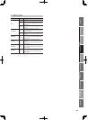
Appendix
USB Memory
Song Player
Digital Recorder
Synthesizer
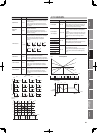
Selecting Sounds Perform. Functions Editing/Eects Other Settings
Rec/Play/Edit Eects Rhythm Pattern
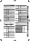
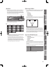
Signal Flow and Parameters
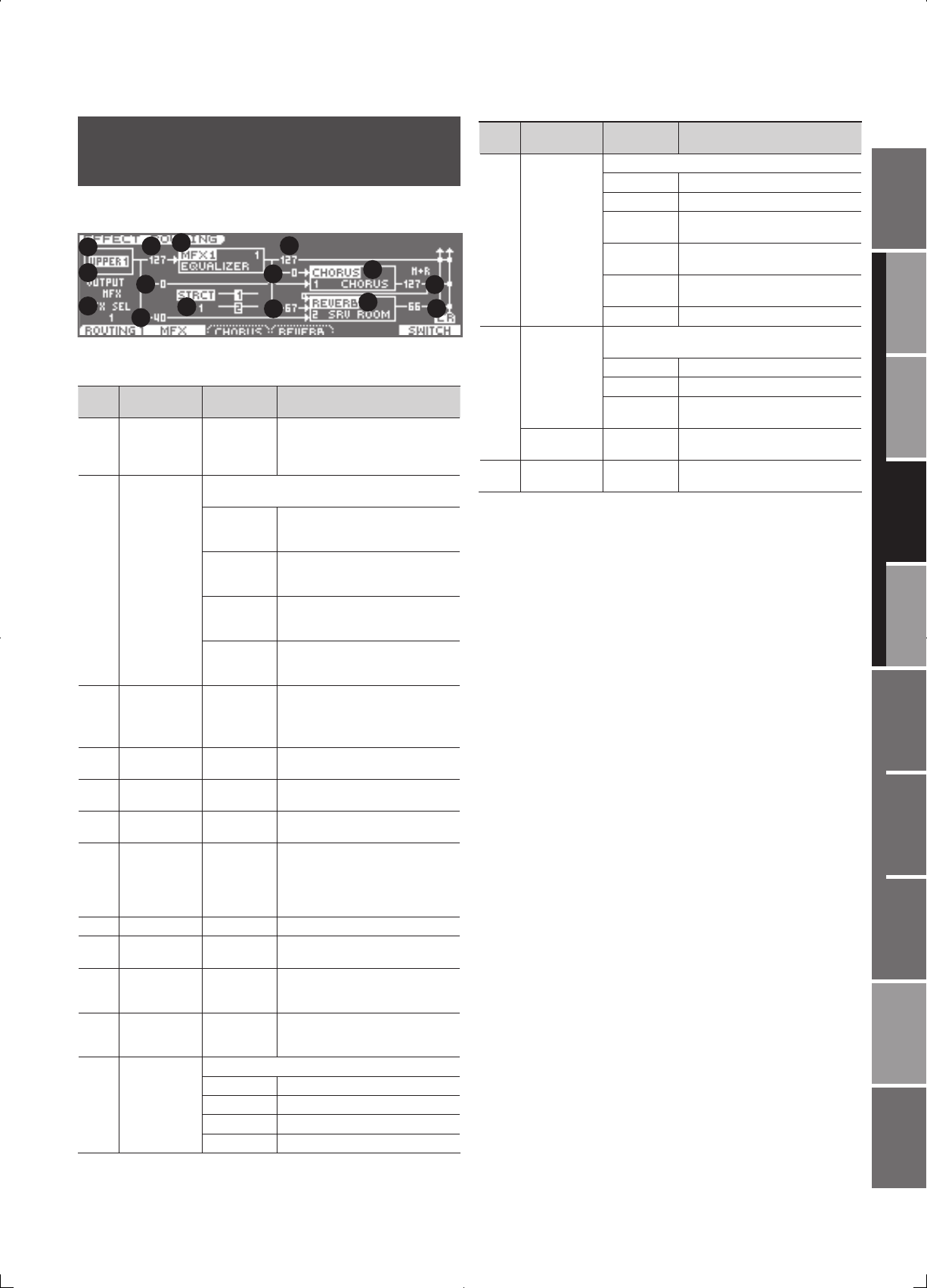
( EFFECT ROUTING)
Here you can make overall settings for e ects, such as the output
destination and level of the various signals.
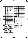
1
2
3
4
5
6
7
8
9
10
11
12
13
14
15
The parameters listed below in 7, 9–11 can be edited for each of the
three multi-e ects (MFX1–MFX2).
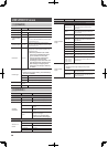
Num-
ber
Parameter Value Explanation
1 Layer Select
UPPER 1,
UPPER 2,
LOWER 1,
LOWER 2
The layer for which to make settings
2
Layer Output
Assign
Speci es how the unprocessed sound of each layer will
be output
MFX
Output in stereo via the multi-e ect.
Chorus and reverb can also be applied
after the multi-e ect.
L+R
Output in stereo from the OUTPUT
jacks without passing through the
multi-e ect
L
Output in mono from the OUTPUT
L jack without passing through the
multi-e ect
R
Output in mono from the OUTPUT
R jack without passing through the
multi-e ect
3 MFX Select 1–2
Multi-e ect used by the layer (choose
one of MFX 1, 2)
4
Layer Output
Level
0–127
Level of signal sent to the destination
speci ed by Layer Output Assign
5
Layer Chorus
Send Level
0–127
Level of signal sent from each layer to
the chorus
6
Layer Reverb
Send Level
0–127
Level of signal sent from each layer to
the reverb
7 MFX Type 0–79
Type of multi-e ect to use (choose
one of 79 types)
For details on each multi-e ect, refer
to “Multi-E ects Parameters (MFX1,
2)” (p. 48).
8 MFX Structure 1–3 How MFX 1, 2 will be combined (p. 46)
9
MFX Output
Level
0–127
Volume of the sound that has been
processed by the multi-e ect
10
MFX Chorus
Send Level
0–127
Amount of chorus applied to the
sound that has been processed by the
multi-e ect
11
MFX Reverb
Send Level
0–127
Amount of reverb applied to the
sound that has been processed by the
multi-e ect
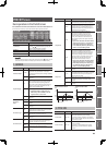
12 Chorus Type
Type of chorus
0 (OFF) Chorus/delay will not be used
1 (CHORUS) Chorus
2 (DELAY) Delay
3 (GM2 CHO) GM2 chorus
Num-
ber
Parameter Value Explanation
13 Reverb Type
Type of reverb
0 (OFF) Reverb will not be used
1 (REVERB) Basic reverb
2 (SRV ROOM)
Reverb that simulates the reverbera-
tion of a room
3 (SRV HALL)
Reverb that simulates the reverbera-
tion of a hall
4 (SRV PLATE)
Simulation of a plate echo (a reverb
device that uses a metal plate)
5 (GM2 REV) GM2 reverb
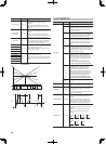
14
Chorus Output
Output destination of the sound that has been
processed by the chorus
MAIN Output in stereo to the OUTPUT jacks
REV Output in mono to reverb
M+R
Output in stereo to the OUTPUT jacks
and in mono to the reverb
Chorus Level 0–127
Volume of the sound that has been
processed by the chorus
15 Reverb Level 0–127
Volume of the sound that has been
processed by the reverb