


52
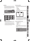
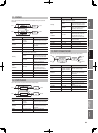
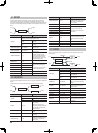
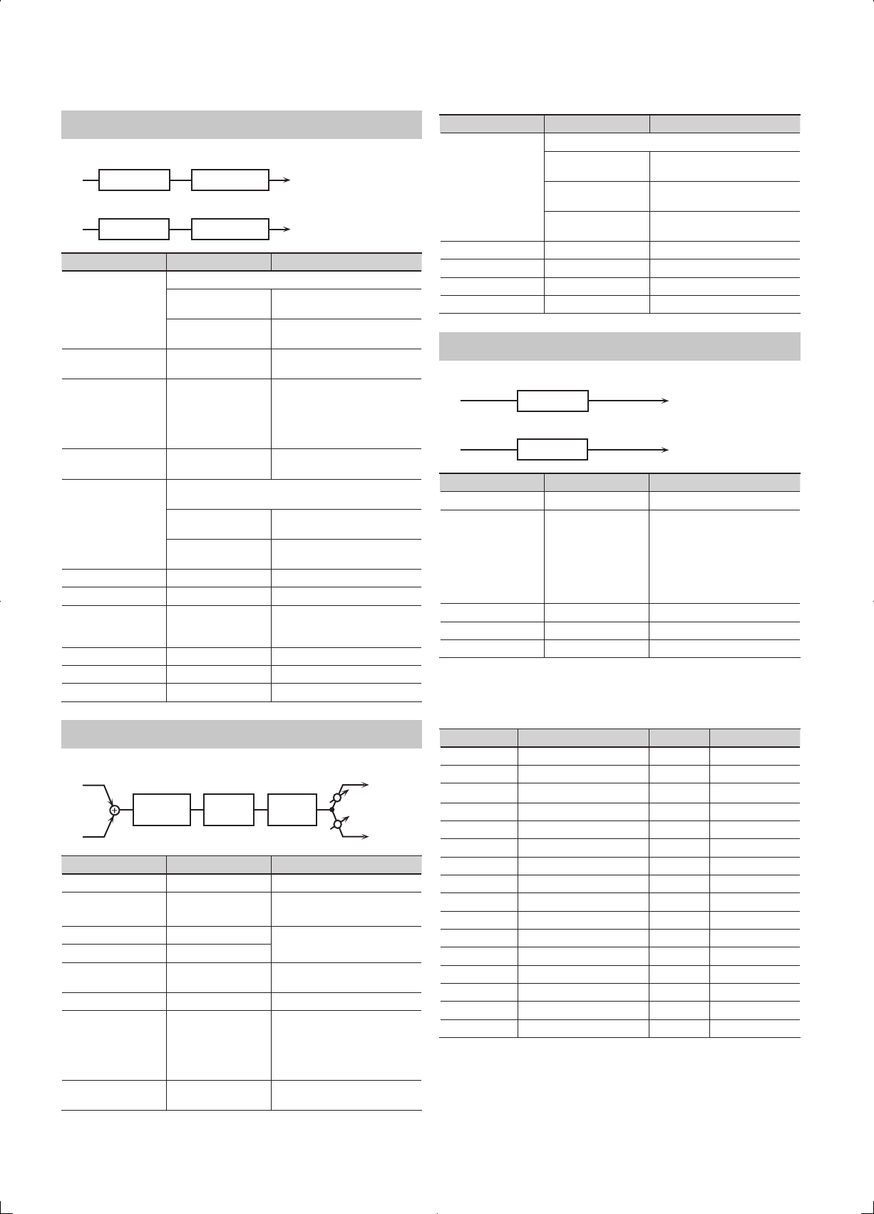
08: AUTO WAH
Cyclically controls a lter to create cyclic change in timbre.
L in
R in
L out
R out
Auto Wah
2-Band EQ
2-Band EQ
Auto Wah
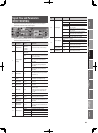
Parameter Value Explanation
Filter Type
Type of lter
LPF
The wah eect will be applied
over a wide frequency range.
BPF
The wah eect will be applied
over a narrow frequency range.
Manual # 0–127
Adjusts the center frequency at
which the eect is applied.
Peak 0–127
Adjusts the amount of the wah
eect that will occur in the range
of the center frequency.
Set a higher value for Q to
narrow the range to be aected.
Sens # 0–127
Adjusts the sensitivity with which
the lter is controlled.
Polarity
Sets the direction in which the frequency will change
when the auto-wah lter is modulated.
UP
The lter will change toward a
higher frequency.
DOWN
The lter will change toward a
lower frequency.
Rate # 0.05–10.00 Hz, note Frequency of modulation
Depth # 0–127 Depth of modulation
Phase # 0–180 deg
Adjusts the degree of phase shift
of the left and right sounds when
the wah eect is applied.
Low Gain -15–+15 dB Gain of the low range
High Gain -15–+15 dB Gain of the high range
Level 0–127 Output Level
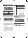
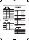
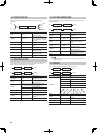
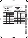
09: HUMANIZER
Adds a vowel character to the sound, making it similar to a human voice.
Formant
2-Band
EQ
L in
R in
Overdrive
L out
R out
Pan R
Pan L
Parameter Value Explanation
Drive Sw OFF, ON Turns Drive on/o.
Drive # 0–127
Degree of distortion
Also changes the volume.
Vowel1 a, e, i, o, u
Selects the vowel.
Vowel2 a, e, i, o, u
Rate # 0.05–10.00 Hz, note
Frequency at which the two
vowels switch
Depth # 0–127 Eect depth
Input Sync Sw OFF, ON
LFO reset on/o
Determines whether the LFO
for switching the vowels is reset
by the input signal (ON) or not
(OFF).
Input Sync Threshold 0–127
Volume level at which reset is
applied
Parameter Value Explanation
Manual #
Point at which Vowel 1/2 switch
0–49
Vowel 1 will have a longer
duration.
50
Vowel 1 and 2 will be of equal
duration.
51–100
Vowel 2 will have a longer
duration.
Low Gain -15–+15 dB Gain of the low frequency range
High Gain -15–+15 dB Gain of the high frequency range
Pan # L64–63R Stereo location of the output
Level 0–127 Output level
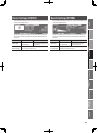
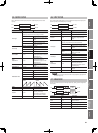
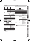
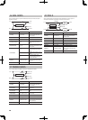
10: SPEAKER SIMULATOR
Simulates the speaker type and microphone settings used to record the speaker sound.
L in
R in
L out
R out
Speaker
Speaker
Parameter Value Explanation
Speaker Type (See the table right.) Type of speaker
Mic Setting 1, 2, 3
Adjusts the location of the
microphone that is recording the
sound of the speaker.
This can be adjusted in three
steps, with the microphone
becoming more distant in the
order of 1, 2, and 3.
Mic Level # 0–127 Volume of the microphone
Direct Level # 0–127 Volume of the direct sound
Level # 0–127 Output Level
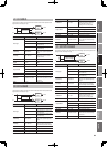
Specications of each Speaker Type
The speaker column indicates the diameter of each speaker unit (in inches) and the
number of units.
Type Cabinet Speaker Microphone
SMALL 1 Small open-back enclosure 10 Dynamic
SMALL 2 Small open-back enclosure 10 Dynamic
MIDDLE Open back enclosure 12 x 1 Dynamic
JC-120 Open back enclosure 12 x 2 Dynamic
BUILT-IN 1 Open back enclosure 12 x 2 Dynamic
BUILT-IN 2 Open back enclosure 12 x 2 Condenser
BUILT-IN 3 Open back enclosure 12 x 2 Condenser
BUILT-IN 4 Open back enclosure 12 x 2 Condenser
BUILT-IN 5 Open back enclosure 12 x 2 Condenser
BG STACK 1 Sealed enclosure 12 x 2 Condenser
BG STACK 2 Large sealed enclosure 12 x 2 Condenser
MS STACK 1 Large sealed enclosure 12 x 4 Condenser
MS STACK 2 Large sealed enclosure 12 x 4 Condenser
METAL STACK Large double stack 12 x 4 Condenser
2-STACK Large double stack 12 x 4 Condenser
3-STACK Large triple stack 12 x 4 Condenser