


40
Input channel operations
Input channel operations
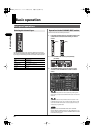
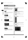
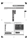
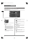
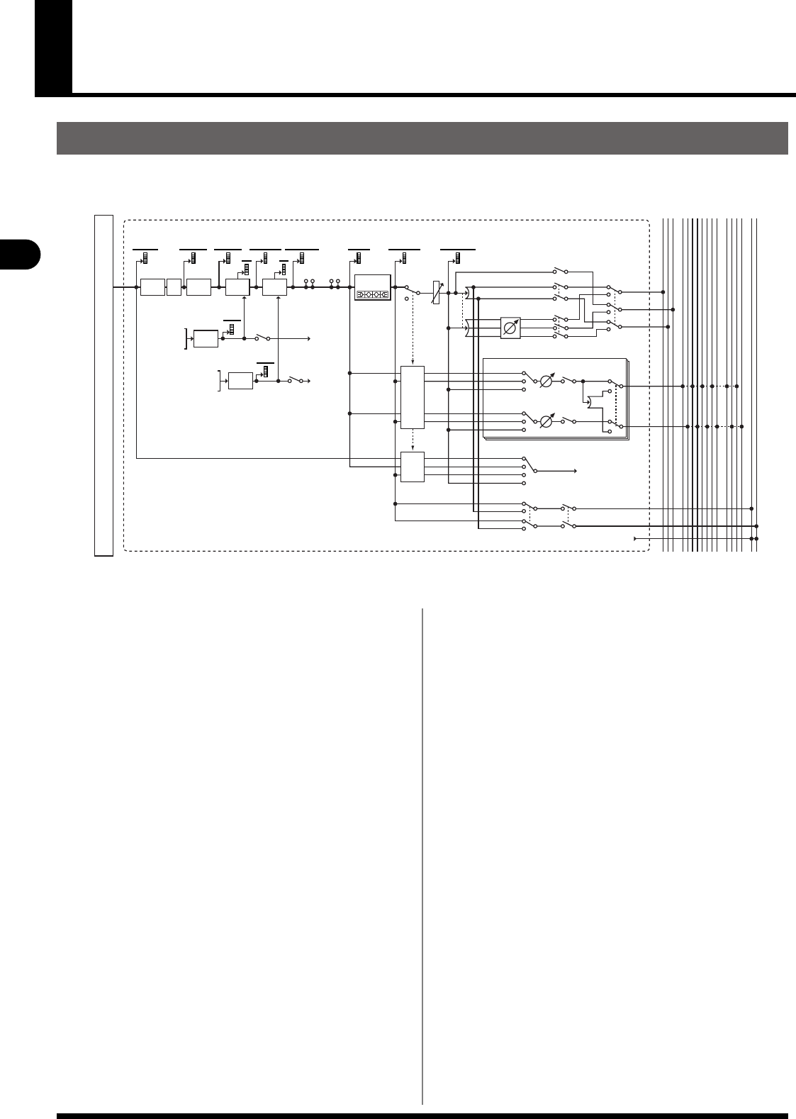
The input channels process the audio signals from the input jacks and internal ports, and send them to the MAIN bus and AUX/MTX buses.
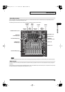
fig.InBlkDia.eps
About the input channels
MAIN
LR LR
SOLOAUX
C
12345678
LRC LR12345678
MAIN SOLOAUX
MTX
1234
1234
MTX
PHASE HPF COMPAT T
PREAMP
KEY-IN
GRGR
KEY-IN
POST HPFPOST ATT POST GATE POST COMP PRE EQ
PRE FADER
PRE EQ
POST FADER
PRE FADER POST FADER
FX
INSERT
MUTE FADER
PA N
PA N
(LCR)
LR ON
MAIN ONCENTER
C ON
EXT FX
INSERT
ON
TO
1, 3...7
TO
2, 4...8
SEND AUX/MTX
LINK
LCR
AUX SEND 1–8, MTX SEND 1–4
PA N
SOLO
KEY-IN
SOLO
TO SOLO
TO SOLO
KEY-IN
SOLO
PRE EQ
PRE FADER
POST FADER
AFL(R)
PFL(R)
AFL(L)
PFL(L)
ONSEND
DIRECT OUT
POINT
AFL ON
KEY-IN SOLO
CH 1–32
GATE/
EXP
KEY-IN
FILTER
MUTE
MUTE
PRE EQ
PRE PHASE
PRE FADER
POST FADER
- SELF POST HPF
- CH 1-32 DIRECT OUT
- REAC A IN1–40
- REAC B IN1–40
- CONSOLE IN1–12
- SELF POST GATE
- CH 1-32 DIRECT OUT
- REAC A IN1–40
- REAC B IN1–40
- CONSOLE IN1–12
TO OUTPUT PATCHBAY
4-BAND
PEQ
KEY-IN
FILTER
INPUT
PATCHBAY
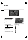
•
INPUT PATCHBAY
This section patches input ports to input channels.
•
PHASE
This reverses the phase of the audio signal.
•
ATT (Attenuator)
This adjusts the input level in the digital domain.
• HPF (High-pass filter)
This is a 12 dB/octave filter that passes the region higher
than the specified frequency.
• GATE/EXPANDER
This is a dynamics processor that can be used as a gate,
expander, or ducking.
•
COMPRESSOR
This is a dynamics processor that can be used as a
compressor.
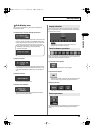
• EXT FX INSERT (External effect insert)
An external effects processor can be inserted at this point
using the rear panel CONSOLE IN5–8 and CONSOLE OUT5–
OUT8 jacks.
•
FX INSERT (Effect insert)
FX1–FX4 can be inserted at this point.
•
4-BAND EQ
This is a 4-band EQ with LO, LO-MID, HI-MID, and HI
frequency bands.
• MUTE
This mutes the channel. The signal sent to the MAIN L/R bus,
the AUX buses, and the direct out will be muted.
•
FADER
This adjusts the send level to the MAIN bus.
•
PAN
This adjusts the left/right panning of the audio signal sent to
the MAIN L/R bus.
• CENTER
When LCR SW is on, this specifies the proportion of the
signal that is sent to MAIN C when PAN is at center.
• LCR SW (LCR switch)
When turn this on, PAN will operate across the three outputs
MAIN L, MAIN C, and MAIN R.
• MAIN SW (Main switch)
This turns the send to the MAIN L/R/C bus on/off.
• LR SW / C SW
These individually turn the send to the MAIN L/R and MAIN C
bus on/off.
• AUX/MTX SENDS
These adjust the send to the AUX/MTX bus.
•
DIRECT OUT POINT
This specifies the position from which the direct out signal is
taken.
M-300_e.book 40 ページ 2010年6月24日 木曜日 午後2時26分