


93
SMPL
1.1
2.13.14.15.15.27.1
■ 1.1–2d: UTILITY
☞“Delete SMPL,” “Copy SMPL,” “Move SMPL,” “Rename
SMPL,” “SMPL To Stereo,” “Delete MS,” “Copy MS,”
“Move MS,” “Rename MS,” “MS To Stereo/MS To
Mono,” “Conv. To Prog,” “Keyboard Disp.” (1.1–3f)
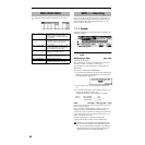
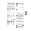
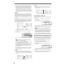
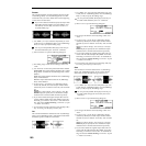
1.1–3: In/Pref (Input/Preference)
Specify the input level from the rear panel AUDIO INPUT 1,
2, and set pan and bus. You can also set other setup parame-
ters.
1.1–3a: Input1, Input2
Here you can make adjustments for the input stage of the
audio signal received at AUDIO INPUT 1 and 2.
These settings are valid only in Sampling mode. These
settings will also be valid when you move from Sam-
pling mode to Global mode.
In modes other than Sampling mode, settings for Audio
Input 1 and 2 are made in “Audio In (Setup for COMBI,
PROG, SEQ)” (GLOBAL 1.1: System, Audio In).
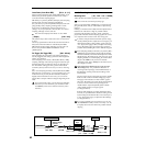
Lvl (Level) [000...127]
Specifies the level of the signal immediately after the analog
audio signal from AUDIO INPUT 1 and 2 is converted into a
digital signal. Normally you will set this to 127.
If you hear distortion even after lowering this level, it is pos-
sible that the distortion is occurring before the A/D con-
verter. Adjust the [LEVEL] knob or the output level of your
external sound source so that the “ADC OVER!” indication
above the “Recording Level” display does not appear.
Pan [L000...C064...R127]
Sets the panning of the analog audio signal from AUDIO
INPUT 1 and 2. Normally you will set Input 1 to L000 and
Input 2 to R127. This allows you to sample a stereo audio
source in stereo (
☞For example settings, p.91, BG p.85).
BUS (BUS(IFX) Select) [L/R, IFX, Off]
Select s the bus.
L/R: Select this when you wish to sample the incoming ana-
log audio signal without applying an insert effect. Normally
you will select L/R.
IFX: Select this when you want to apply the insert effect to
the analog audio input signal while it is being sampled.
(
☞p.158)
Off: The analog audio signal will not be input.
1.1–3b: Create (Create Zone Preference)
These settings determine the initial state of the indexes that
are created when you press the [F6] (“CREATE”) key (1.1–
1c, 4.1–1c). Each new index will be created according to the
settings you make here, but you are free to modify the set-
tings later.
Pstn (Position) [R, L]
Specifies whether the new index will be created at the right
or left of the selected index.
R (Right): The new index will be created at the right of the
currently selected index.
L (Left): The new index will be created at the left of the cur-
rently selected index.
Range (Zone Range) [001...127]
Specifies the key range of the zone of the newly created
index.
001: A single note of the keyboard will be the index. The
sample of the index will sound at its original key when you
play that note. This setting can be used similarly to pad
(keyboard) type samplers.
002...127: The sample will change pitch in semitone steps
across the specified number of keys, centered on the original
key “Orig.K” (1.1–1b, 4.1–1b). If “Constant Pitch” (4.1–2a) is
checked, the pitch will not change.
Orig.K (Original Key Position) [Btm, Cntr, Top]
Specifies where the original key will be located in the zone
(specified by “Zone Range”) for a newly created index.
Btm (Bottom): The lowest key in the zone will be the origi-
nal key.
Cntr (Center): The middle key in the zone will be the origi-
nal key.
Top: The top key in the zone will be the original key.
1.1–3c: Auto Loop
Auto Loop (Auto Loop On) [Off, On]
On (checked): The recorded sample will automatically be
played with looping turned on (
☞“3.1: Loop Edit”).
1.1–3d: Metro (Count Down REC Metronome)
BUS (Metronome BUS) [L/R, 1, 2]
Specifies the output destination of the metronome sound
played by “Count Down” (1.1–2b).
L/R: The metronome will be output from OUTPUT (MAIN)
L/MONO, R, and the headphones.
1, 2: The metronome will be output from OUTPUT (INDI-
VIDUAL) 1 or 2 respectively.
Lvl (Metronome Level) [000...127]
Specifies the level of the metronome sound played by
“Count Down.”
1.1–3e: Recording Level
[–inf, –72.0... 0.0...+18.0]
Adjusts the signal level at the final stage of sampling (☞1.1–
2c).
■ 1.1–3f: UTILITY
For details on how to select the desired utility function, refer
to “PROG 1.1–1c: UTILITY.”
1.1–3a
1.1–3b
1.1–3c
1.1–3e 1.1–3f
1.1–3d