


255
Appendices
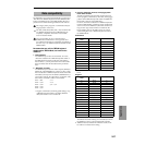
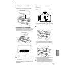
2–1. Detaching cover “A” for the EXB-SMPL
1 Use a screwdriver to remove one screw from cover “A.”
When the TRITON Le is upturned and the rear panel is
toward you, cover “A” is the large one at the right.
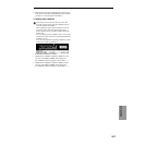
2–2. Detaching cover “B” for DRAM SIMM
1 Use a screwdriver to remove one screw from cover “B.”
When the TRITON Le is upturned and the rear panel is
toward you, cover “B” is the small one at the left.
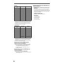
3–1. Installing the EXB-SMPL
You must leave the AC/AC power supply disconnected
until you finish the entire process of removing the
cover, installing the option board or memory, and reat-
taching the cover.
1 Make sure that cover “A” has been removed. (☞“1. Prep-
arations for installation,” “2–1. Detaching cover “A” for
the EXB-SMPL”)
2 Remove the EXB-SMPL from its packing pouch.
3 Note that screws and washers are attached to two corners
of the board.
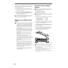
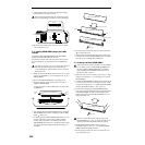
4 Lightly bend the flat cable as shown in the diagram
below.
5 From the rear panel of the TRITON Le, remove the three
screws from the cover of the EXB-SMPL installation
opening, and remove the EXB-SMPL cover.
The cover (EXB-SMPL) and the three screws you
removed will not be used. Do not leave them inside the
TRITON Le.
6 Place the EXB-SMPL so that its jacks, switch, knob, and
SCSI connector extend from the rear of the TRITON Le,
and while using one hand to support the EXB-SMPL in
position, tighten the included three screws from the rear
panel.
7 Use the two screws to attach the EXB-SMPL to the corre-
sponding brackets inside the TRITON Le.
Before the screws are tightened, the EXB-SMPL will
float slightly above the brackets. If at this time you
apply excessive force to the EXB-SMPL, the screws or
washers may come out.
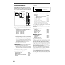
Slots for DRAM SIMM modules
When cover “B” is removed
Catches
Rear panel
Screw
Bend
Washer
Cover
(for EXB-SMPL)