


16
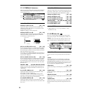
4.1–4: lfoMod (LFO Modulation)
Here you can use the filter 1 LFO to apply cyclic modulation
to the cutoff frequency of filter 1 (for oscillator 1) to create
cyclical changes in tone.
4.1–4a: Filter LFO1 Modulation
Intensity to A (LFO1 Int. to A) [–99…+99]
Specifies the depth and direction of the modulation that
OSC1 LFO1 (set by “OSC1 LFO1” 5.3–1a) will have on the
cutoff frequency of filter 1A.
Negative (–) settings will invert the phase.
Intensity to B (LFO1 Int. to B) [–99…+99]
Specifies the depth and direction of the modulation that
OSC1 LFO1 will have on the cutoff frequency of filter 1B
(
☞“Intensity to A (LFO1 Int. to A)”).
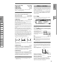
JS–Y Int. to A (LFO1 JS–Y Int. to A) [–99…+99]
By moving the joystick in the –Y direction (toward yourself),
you can control the depth at which OSC1 LFO1 modulates
the cutoff frequency of filter 1A. This parameter specifies the
depth and direction of the control.
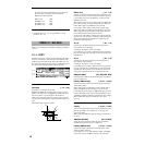
For example, as this value is raised, OSC1 LFO1 will have a
correspondingly greater effect on filter 1 when the joystick is
moved in the –Y direction.
JS–Y Int. to B (LFO1 JS–Y Int. to B) [–99…+99]
By moving the joystick in the –Y direction (toward yourself),
you can control the depth at which OSC1 LFO1 modulates
the cutoff frequency of filter 1B. This parameter specifies the
depth and direction of the control. (
☞“JS –Y Int. to A (LFO1
JS–Y Int. to A)”)
AMS (LFO1 AMS) [Off, (PEG, FEG, AEG, KT, EXT)]
Selects a source that will control the depth and direction of
cutoff frequency change for both filters 1A and 1B (
☞p.212
“AMS List”).
Int. to A (LFO1 AMS Int. to A) [–99…+99]
Specifies the depth and direction of the effect that “AMS
(LFO1 AMS)” will have on filter 1A.
For example, if “AMS” is AfterT, higher settings of this
parameter will allow greater change to be applied to OSC1
LFO1 when you apply pressure to the keyboard.
Int. to B (LFO1 AMS Int. to B) [–99…+99]
Specifies the depth and direction of the effect that “AMS
(LFO1 AMS)” will have on filter 1B (
☞“Int. to A (LFO1 AMS
Int. to A)”).
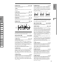
4.1–4b: Filter LFO2 Modulation
Adjusts the depth of the cyclic modulation applied by OSC1
LFO2 (set by “OSC1 LFO 2” 5.3–2) to the cutoff frequency of
filters 1A and 1B (
☞“Filter LFO 1 Modulation” 4.1–4a).
Intensity to A (LFO2 Int. to A) [–99…+99]
Intensity to B (LFO2 Int. to B) [–99…+99]
JS–Y Int. to A (LFO2 JS–Y Int. to A) [–99…+99]
JS–Y Int. to B (LFO2 JS–Y Int. to B) [–99…+99]
AMS (LFO2 AMS) [Off, (PEG, FEG, AEG, KT, EXT)]
Int. to A (LFO2 AMS Int. to A) [–99…+99]
Int. to B (LFO2 AMS Int. to B) [–99…+99]
■ 4.1–4c: UTILITY
☞“Write Program” (1.1–1c), “Copy Oscillator,” “Swap
Oscillator” (2.1–1d)
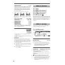
4.1–5: EG (Filter1 EG)
Here you can make settings for the EG that will produce
time-varying changes in the cutoff frequency of filters 1A
and 1B.
The depth of the effect that these settings will have on the
filter 1 cutoff frequency is determined by “Filter EG” (4.1–
2b).
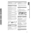
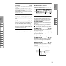
4.1–5a: Filter1 EG
Specifies the time-varying change produced by the filter 1
EG.
L (Level):
The result will depend on the filter that was selected in
“Type (Filter Type)” (4.1–1a). For example with the Low
Pass Resonance filter, positive (+) values of “Int. to A” (4.1–
2b) will cause the tone to be brightened by positive (+) lev-
els, and darkened by negative (–) levels.
S (Start Level) [–99…+99]
Specifies the change in cutoff frequency at the time of note-
on.
A (Attack Level) [–99…+99]
Specifies the change in cutoff frequency after the attack time
has elapsed.
B (Break Point Level) [–99…+99]
Specifies the change in cutoff frequency after the decay time
has elapsed.
S (Sustain Level) [–99…+99]
Specifies the change in cutoff frequency that will be main-
tained from after the slope time has elapsed until note-off
occurs.
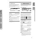
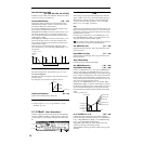
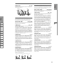
4.1–4a
4.1–4b
4.1–4c
Change in cutoff
Low setting High setting
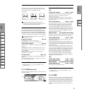
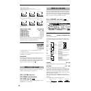
4.1–5a
4.1–5b
4.1–5d
4.1–5c