


161
Effect
– Setting for drum program –
If a drum program has been selected for a timbre in Combi-
nation mode or for a track in Sequencer mode, you will be
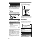
able to select DKit for the “BUS Select” parameter. If this is
selected, the “BUS (BUS Select)” (GLOBAL 5.1–3a) settings
for each individual key will be used, and will be sent to the
bus for each drum instrument. In this case, the send level
will be determined by multiplying the value of the “S1
(Send1(MFX1))” and “S2 (Send2(MFX2))” settings of each
key in the drum kit by the value of the “S1 (Send1(MFX1))”
and “S2 (Send2(MFX2))” settings that you make here. (For
the drum instruments of keys whose drum kit “BUS (BUS
Select)” parameter is set to IFX, this is determined by “S1
(Send1(MFX1))” and “S2 (Send2(MFX2))” after the signal
has passed through IFX.) If L/R or Off is selected, the send
levels specified by PROG 7.1–1a “OSC1 Send 1” and “Send
2” will be multiplied by the “S1 (Send1(MFX1))” and “S2
(Send2(MFX2))” settings that you make here. (This is the
same as when “Oscillator Mode” is Single or Double.) If
IFX are selected, the “S1 (Send1(MFX1))” and “S2
(Send2(MFX2))” after the specified insert effect will be used.
If 1, 2 or 1/2 are selected, “S1 (Send1(MFX1))” and “S2
(Send2(MFX2))” will be ignored.
2–3. Sampling Mode (if the separately sold EXB-
SMPL option is installed)
You cannot use the Master Effects and Master EQ in Sam-
pling mode.
2–4. Audio Input (if the separately sold EXB-SMPL
option is installed)
In Program, Combination, and Sequencer modes, you can
apply the Insert Effect, Master Effects and Master EQ to the
signals input from AUDIO INPUTs 1 and 2. These signals
are routed to the TRITON Le’s effects, according to the GLO-
BAL 1.1: System, Audio In page setting.
The send levels from input 1 and 2 to the master effects are
specified by the “Send 1” and “Send 2” (GLOBAL 1.1–4a/b)
values. These settings become effective only when “BUS
Select” is set to L/R or Off. If IFX is selected, use the “S1
(Send1(MFX1))” and “S2 (Send2(MFX2))” parameters (
☞“3.
Mixer”). If 1, 2, or 1/2 is selected, the Send Level 1 and Send
2 settings are ignored.
These settings are ignored in Sampling mode.
Use 7.2: Ed–MasterFX (or Master FX)in Program, Combina-
tion, and Sequencer modes to set the Master Effects and
Master EQ.
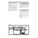
3. Mixer
The send levels determine the input levels of oscillators
(Program), timbres (Combination), tracks (Sequencer) that
are routed to the Master Effects. The 7.2: Ed–MasterFX (or
Master FX) in all modes enable you to set the output levels
and Master EQ gain values, and connect the Master Effects
in series (chain).
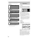
3–1. Rtn (Return1, Return2)
These specify the output levels from MFX1 and MFX2
respectively. The left value of the “W/D” specified for the
effect selected in MFX 1 or 2 will be the output level of the
master effect; e.g., 25% for 25:75, 100% for Wet, and 0% for
Dry. This level multiplied by the “Rtn (Return 1, Return 2)”
value will be sent to the L/R bus, and will be mixed with the
7.1–1a “BUS Select” L/R or 7.2–1a“BUS Select” L/R output
sound.
For example, with MFX1 “W/D” set to 50:50 (50%) and “Rtn
(Return1)” set to 64 (50%), the resultant effect level will be
25%. The effect level is maximum (100%) when “W/D” is set
to “Wet” and “Rtn (Return1)” is set to 127.
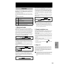
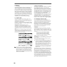
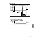
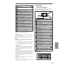
3–2. MFX Chain
If you check the “MFX Chain” check box, the signal will be
routed between MFX1 and MFX2.
The following figure indicates that the output from
“MFX1:16: Stereo Chorus” is added to “MFX2: 52: Reverb
Hall” input.
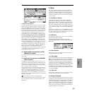
3–3. Chain Direction
Specify the direction of the connection when the signal is
routed between MFX1 and MFX2.
3–4. Chain Signal
This parameter enables you to select signals routed between
MFX1 and 2. If the chain direction (order) is from MFX1 to
MFX2, selecting LR Mix will cause the stereo L/R outputs
from MFX1 to be mixed and input to MFX2. This setting is
useful when you wish to serially connect delays that are
panned to L and R (e.g., “43: LCR Delay”). Selecting L Only
or R Only will cause only one channel of stereo outputs
from MFX1 to be input to MFX2. This setting is suitable for a
chain connection of a reverb effect and a modulation effect
such as 16: St. Chorus.
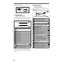
3–5. Chain Level
This parameter determines the level of signals routed from
one MFX to the other MFX in a chain connection.
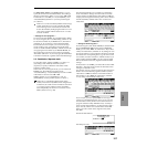
3–6. Master EQ Gain[dB]
These parameters are used to set the gain of the Low, Mid,
and High stereo three-band EQ that is located right before
AUDIO OUTPUT (MAIN) L/MONO and R. Low and High
EQs are of the shelving type, and Mid EQ is a band type
equalizer. These settings are linked with the Low, Mid, and
High “Gain” parameters of the MEQ page. Use this MEQ
page to set the center frequency, band width (for Mid), and
dynamic modulation of the EQ bands.
(1)
(2)