


256
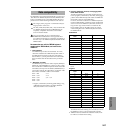
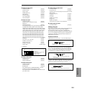
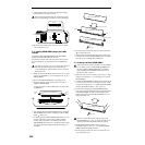
8 Attach the flat cable as shown in the diagram. Plug the
cable all the way into the connector.
When connecting the flat cable, be careful not to touch
any part other than the connector on the circuit board.
9 Reversing the procedure by which you removed cover
“A,” re-attach the cover.
3–2. Installing DRAM SIMM (sample data RAM)
modules
Install the 16 Mbyte DRAM SIMM (sample data RAM)
included with the EXB-SMPL into the slot.
The memory module will work correctly in either slot. For
ease of installation, we suggest that you use SIMM slot 2
first.
You must leave the AC/AC power supply disconnected
until you finish the entire process of removing the
cover, installing the option board or memory, and reat-
taching the cover.
1 Make sure that cover “B” has been removed. (☞“1. Prep-
arations for installation,” “2–2. Detaching cover “B” for
DRAM SIMM”)
2 Remove the DRAM SIMM from its packing pouch.
3 Verify the location of the slot into which you wish to
install the DRAM SIMM.
Looking from the rear of the TRITON Le, the nearer slot
is SIMM slot 2.
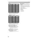
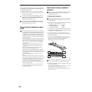
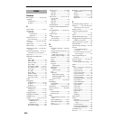
4 The notched side of the DRAM SIMM is PIN 1. Install the
DRAM SIMM with its PIN 1 side aligned with the PIN 1
mark (
) of the slot.
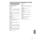
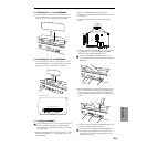
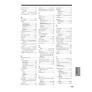
5 At a slant, press the DRAM SIMM firmly all the way into
the slot, and raise it to the vertical position until the
catches of the slot click into the locking holes of the
DRAM SIMM. When doing so, pressing the catches of the
slot apart to the left and right will help the board go in
smoothly.
6 Reversing the procedure by which you removed cover
“B,” re-attach the cover.
7 When all steps have been completed, turn on the power
and make sure that the DRAM SIMM has been installed
correctly. (☞“4. Checking after installation”)
3–3. Installing additional DRAM SIMM’s
A maximum of two memory modules can be installed.
If you want to use two 32 Mbyte DRAM SIMM mod-
ules, the 16 Mbyte DRAM SIMM that you installed
when installing the EXB-SMPL must be removed as
described in step
3 below.
1 Make sure that cover “B” has been removed. (☞“1. Prep-
arations for installation,” “2–2. Detaching cover “B” for
DRAM SIMM”)
2 A 16 Mbyte DRAM SIMM is installed in the nearer slot. If
you want to add only one more memory module, install
it in the remaining slot. (☞”3–2. Installing DRAM SIMM
(sample data RAM) modules,” steps
4 and 5.)
3 If you will be installing two DRAM SIMM modules,
remove the currently-installed memory. Spread the tabs
of the DRAM SIMM slot apart to left and right (after
releasing the catches), tilt the DRAM SIMM over at an
angle, and pull it out.
When you spread the catches of the slot apart, the
DRAM SIMM may pop out vigorously and fall into an
opening (inside the instrument). Please be careful
4 Install DRAM SIMM modules in the two slots as
described in steps
4 and 5 of “3–2. Installing DRAM
SIMM (sample data RAM) modules.”
5 Reversing the procedure by which you removed cover
“B,” re-attach the cover.
Press in all the way
ConnectorConnector
Press in all the way
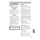
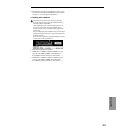
EXB-SMPL
Chassis to which the board is attached
Screw
Washer
1PIN
72PIN
Rear panel
Rear side of the DRAM SIMM
Catches
Locking
hole
Locking
hole
Notch
Rear panel
Rear side of DRAM SIMM
Rear side of DRAM SIMM
Rear side of DRAM SIMM
Catch
Catch
Press in at a slant
Raise to vertical
Rear panel
Rear side of DRAM SIMM