


PROG
1.1
2.12.23.14.14.25.15.25.36.17.17.2
PROG
1.1
2.12.23.14.14.25.15.25.36.17.17.2
15
Int. to B (KBDTrk Int. to B) [–99...+99]
Specifies the depth and direction of the effect on filter 1B
produced by keyboard tracking. (
☞“Int. to A (KBDTrk Int.
to A)”)
4.1–2b: Filter EG
Int. to A (Intensity to A) [–99…+99]
Specifies the depth and direction of the effect that the time-
varying changes created by the filter 1 EG will have on the
filter 1A cutoff frequency.
With positive (+) settings, the sound will become brighter
when the EG levels set by Filter 1 EG “L (Level)” and “T
(Time)” parameters (4.1–5a) are in the “+” area, and darker
when they are in the “–” area.
With negative (–) settings, the sound will become darker
when the EG levels set by Filter 1 EG “L (Level)” and “T
(Time)” parameters are in the “+” area, and brighter when
they are in the “–” area.
Int. to B (Intensity to B) [–99…+99]
Specifies the depth and direction of the effect that the time-
varying changes created by the filter 1 EG will have on the
filter 1B cutoff frequency. (
☞“Int. to A (Intensity to A)”)
Vel to A (Velocity to A) [–99…+99]
This parameter specifies the depth and direction of the effect
that velocity will have on the time-varying changes created
by the filter 1 EG (as set by “Filter 1 EG” 4.1–5) to control the
filter 1A cutoff frequency.
With positive (+) values, playing more strongly will cause
the filter 1 EG to produce greater changes in cutoff fre-
quency. With negative (–) values, playing more strongly will
also cause the filter 1 EG to produce greater changes in cut-
off frequency, but with the polarity of the EG inverted.
Vel to B (Velocity to B) [–99…+99]
This parameter specifies the depth and direction of the effect
that velocity will have on the time-varying changes created
by the filter 1 EG to control the filter 1B cutoff frequency.
(
☞“Vel to A (Velocity to A)”)
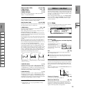
■ 4.1–2c: AMS, Into to A, Int to B
AMS (Filter EG AMS) [Off, (EXT)]
Indicates the source that will control the depth and direction
of the effect that the time-varying changes produced by the
filter 1 EG will have on the cutoff frequency of filters 1A and
1B (
☞p.212 “AMS List”).
Int. to A (AMS Int. to A) [–99…+99]
Specifies the depth and direction of the effect that “AMS
(Filter EG AMS)” will have on filter 1A.
For details on how this will apply, refer to “Int. to A (Inten-
sity to A).”
Int. to B (AMS Int. to B) [–99…+99]
Specifies the depth and direction of the effect that “AMS
(Filter EG AMS)” will have on filter 1B. (
☞“Int. to A (Inten-
sity to A).”)
The sum of the settings for “Int. to A (B),” “Vel to A
(B),” and “Int. to A (B) (AMS Int. to A/B)” will deter-
mine the depth and direction of the effect produced by
the filter EG.
■ 4.1–2d: UTILITY
☞“Write Program” (1.1–1c), “Copy Oscillator,” “Swap
Oscillator” (2.1–1d)
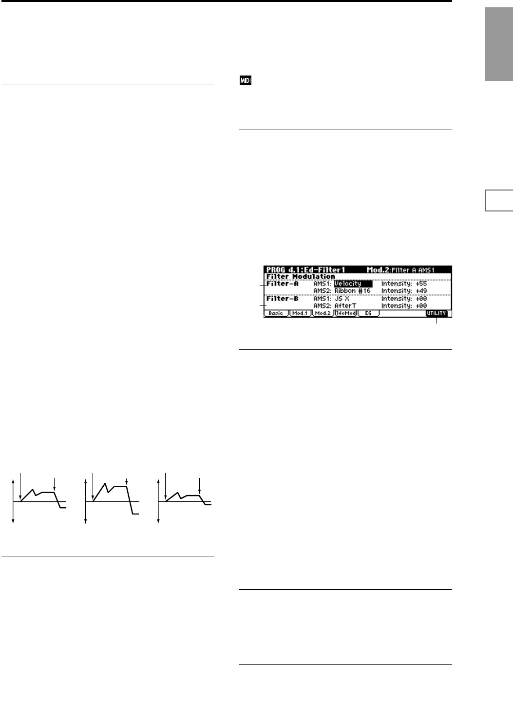
4.1–3: Mod.2 (Filter1 Modulation2)
Indicates settings for the controller that will modify the tone
by applying modulation to the filter 1 cutoff frequency “Fre-
quency (A/B Frequency).”
If “Type (Filter Type)” (4.1–1a) is Low Pass Resonance, the
filter B parameters will not be displayed.
4.1–3a: Filter-A Modulation
AMS1 (Filter A AMS1) [Off, (PEG, AEG, EXT)]
Indicates the source that will control modulation of the filter
1A cutoff frequency (
☞p.212 “AMS List”).
Intensity (A AMS1 Intensity) [–99…+99]
Specifies the depth and direction of the effect that “AMS1
(Filter A AMS1)” will have.
When “AMS1 (Filter A AMS1)” is JS X, a positive (+) value
for this parameter will cause the cutoff frequency to rise
when the joystick is moved toward the right, and fall when
the joystick is moved toward the left. With a negative (–)
value for this parameter, the opposite will occur.
This value is added to the setting of the Filter A “Frequency
(A Frequency)”(4.1–1b).
AMS2 (Filter A AMS2) [Off, (PEG, AEG, EXT)]
Intensity (A AMS2 Intensity) [–99…+99]
Selects “AMS2 (Filter A AMS2),” and specify the depth and
direction of the effect that the selected source will have
(
☞“AMS1,” “Intensity”).
■ 4.1–3b: Filter-B Modulation
This will be displayed when “Type (Filter Type)” (4.1–1a) is
Low Pass & High Pass.
Two alternate modulation sources can be used to modulate
the cutoff frequency of filter 1B (
☞“Filter-A Modulation”).
■ 4.1–3c: UTILITY
☞“Write Program” (1.1–1c), “Copy Oscillator,” “Swap
Oscillator” (2.1–1d)
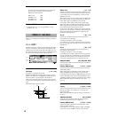
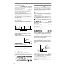
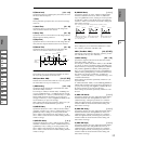
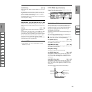
Changes in cutoff frequency
Softly played
(The setting of Intensity to A (4.1–2b))
Strongly played
Setting to –
Strongly played
Setting to +
Note-on
Note-off
Note-on
Note-off
Note-on
Note-off
4.1–3a
4.1–3b
4.1–3c