21
a
System Components
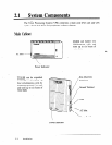
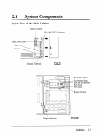
Main Cabinet Components
I-
TVS 75
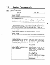
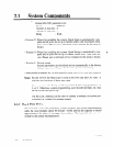
Ground Terminal
TVS 100
Connect the frame of the main unit to ground.
EIA Connector (RS-232C)
Connecting a data terminal to the VPS unit via EIA connector allows the System
Administrator to set the system parameters of the VPS. A serial printer can be
connected to this port to print the reports.
Fuse
If the Power Indicator goes off while the system is running, the fuse may have
been blown. When replacing the fuse with the new one, be sure the TVS75’s
Power Cable is disconnected or the TVSlOO’s Power Switch is turned off.
AC Power Jack
Connect the Power Cable to an AC outlet dedicated to the VPS unit.
Rotary Switch
The rotary switch is used, for example, when performing initial parameters set-
tings.
Power Indicator
Power Indicator
Connecting the Power Cable starts the
When turning on the Power Switch,
system beginning with the self test.
this indicator flashes while setting up
This indicator flashes while setting up
the system, then it lights to show the
the system, then it lights to show the
system is on-line mode.
system is on-line mode.
Power Switch
When making any connections or
Pressing the Power Switch starts the
opening the cover, be sure the Power
system beginning with the self test.
Cable is disconnected. When making any connections or
opening the cover, be sure the Power
Switch is turned off.
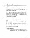
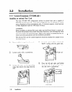
Grounding Strap
To protect the printed circuit board
from static electricity, first discharge
any body static by touching the
grounding strap.
2-4
Installation


