


58
Creating a Patch
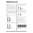
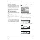
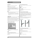
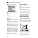
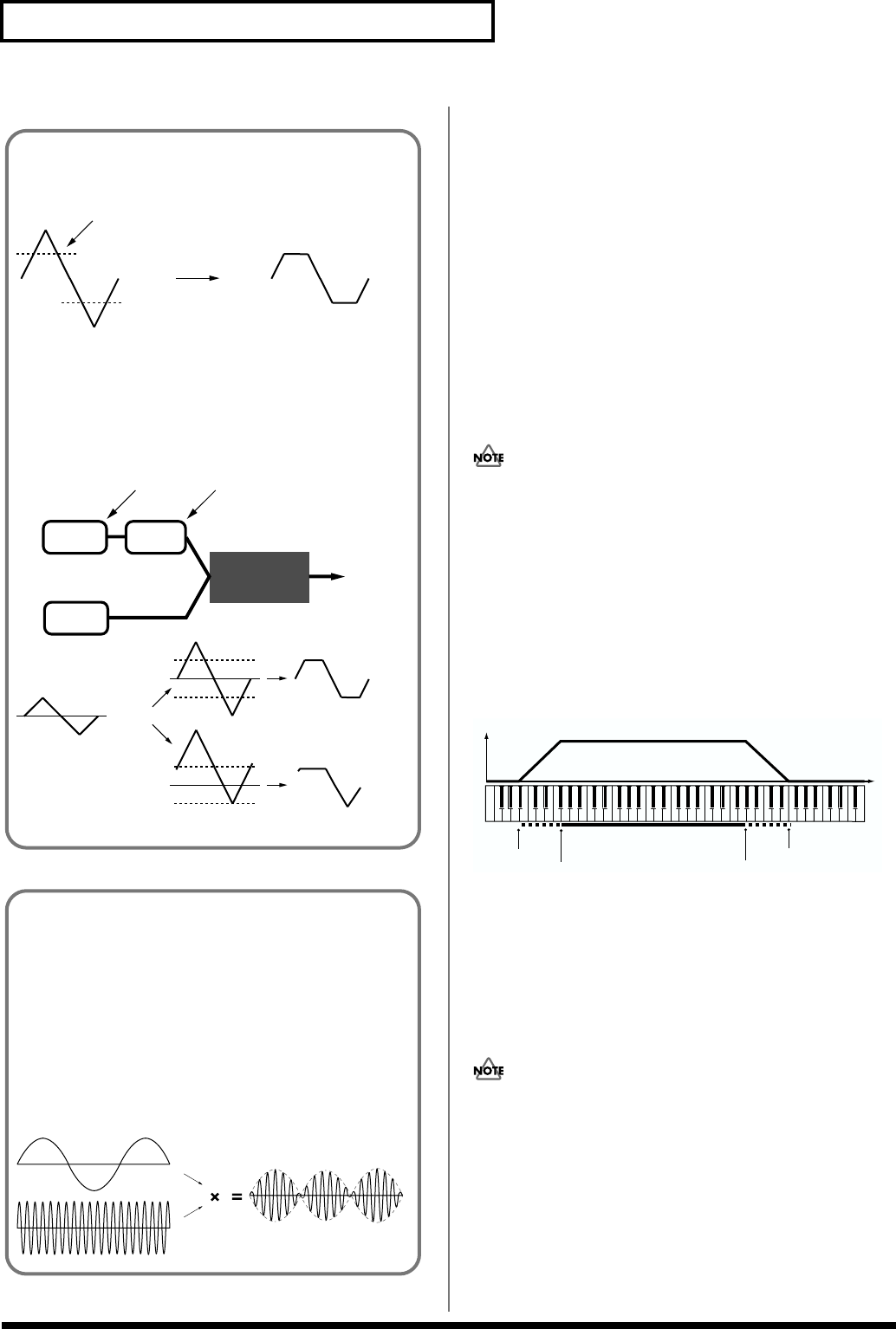
Key Fade Lower (Keyboard Fade Width Lower)
This determines what will happen to the tone’s level when a note
that’s lower than the tone’s specified keyboard range is played.
Higher settings produce a more gradual change in volume. If you
don’t want the tone to sound at all when a note below the keyboard
range is played, set this parameter to “0.”
Value: 0–127
Key Range Lower (Keyboard Range Lower)
Specifies the lowest note that the tone will sound for each tone.
Value: C-1–UPPER
Key Range Upper (Keyboard Range Upper)
Specifies the highest note that the tone will sound for each tone.
Value: LOWER–G9
If you attempt to raise the lower key higher than the upper key,
or to lower the upper key below the lower key, the other value
will be automatically modified to the same setting.
Key Fade Upper (Keyboard Fade Width Upper)
This determines what will happen to the tone’s level when a note
that’s higher than the tone’s specified keyboard range is played.
Higher settings produce a more gradual change in volume. If you
don’t want the tone to sound at all when a note below the keyboard
range is played, set this parameter to “0.”
Value: 0–127
fig.Key Range.e
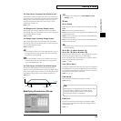
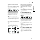
TMT Vel Control (TMT Velocity Control Switch)
TMT Velocity Control determines whether a different tone is played
(ON) or not (OFF) depending on the force with which the key is
played (velocity).
When set to “RND,” the patch’s constituent tones will sound
randomly, regardless of any Velocity messages.
Value: OFF, ON, RND
Instead of using Velocity, you can also have tones substituted
using the Matrix Control (p. 55). However, the keyboard velocity
and the Matrix Control cannot be used simultaneously to make
different tones to sound. When using the Matrix Control to
switch tones, set the TMT Vel Control parameter to “OFF.”
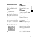
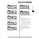
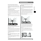
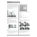
Booster
The Booster is used to distort the incoming signal.
fig.Booster-1.e
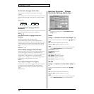
In addition to using this to create distortion, you can use the
waveform (WG1) of one of the tones as an LFO which shifts the
other waveform (WG2) upward or downward to create
modulation similar to PWM (pulse width modulation). This
parameter works best when you use it in conjunction with the
Wave Gain parameter (PATCH/Wave) (p. 59).
fig.Booster-2.e
Booster level
TVA
WG1
WG2
Booster
Adds to WG1
Shift in waveform by WG1
Distorted area of the
Waveform changes
WG2
Uses WG1 as LFO
Adjusts WG1 output
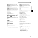
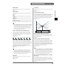
Ring Modulator
A ring modulator multiplies the waveforms of two tones with
each other, generating many new overtones (inharmonic
partials) which were not present in either waveform. (Unless
one of the waveforms is a sine wave, evenly-spaced frequency
components will not usually be generated.)
As the pitch difference between the two waveforms changes the
harmonic structure, the result will be an unpitched metallic
sound. This function is suitable for creating metallic sounds
such as bells.
fig.Ring Mod
Range Lower
Range Upper
Fade Lower
Fade Upper
Level
Pitch