


Chapter 8. Appendix
193
Section 3. Individual Parameter Transmission
(Model ID=45H or 42H)
Individual Parameter Transmission transmits data (or requests data) for one para-
meter as one exclusive message (one packet of "F0 ..... F7").
In Individual Parameter Transmission, you must use the Address and Size listed in
the following "Parameter Address Map". Addresses marked at "#" cannot be used as
starting addresses.
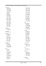
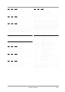
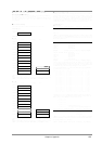
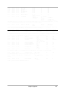
■ Address Block map
An outlined address map of the Exclusive Communication is as follows;
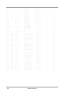
<Model ID = 45H>
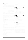
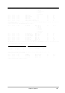
<Model ID = 42H>
● Port-A
* The blocks displayed in gray cannot be accessed in Mode-1 (Single Module
mode).
* Blocks listed as "#A" are parameter blocks which are common to the entire device
in Mode-1, and valid only for Parts A01 - A16 in Mode-2 (Double Module mode).
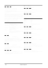
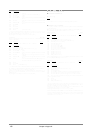
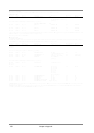
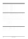
● Port-B
* The blocks displayed in gray cannot be accessed in Mode-1 (Single Module
mode).
* Blocks listed as "#B" are parameter blocks which are common to the entire device
in Mode-1, and valid only for Parts B01 - B16 in Mode-2 (Double Module mode).
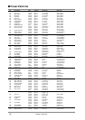
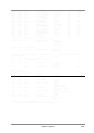
■ Parameter address map
This map indicates address, size, Data (range), Parameter, Description, and Default
Value of parameters which can be transferred using "Request data 1 (RQ1)" and
"Data set 1 (DT1)".All the numbers of address, size, Data, and Default Value are
indicated in 7-bit Hexadecimal-form. Numbers in the explanatory column are given
in decimal notation. The MODEL ID = 45H parameters are related to LCD display.
The MODEL ID = 42H parameters at address 5* ** ** are not given in this map. The
parameters for address 5* ** ** are the same format as those at at address 4* ** **.
< MODEL ID = 45H >
● Display data
Address(H) Size(H) Data(H) Parameter Description Default Value(H)
10 00 00 00 00 20 20-7F Displayed Letter 32-127(ASCII) ---
10 00 01#
10 00 02#
:
10 00 1F#
* When this message is received, a character string specified by the data will be
temporarily displayed in the INSTRUMENT display area. A character string of 1 to
32 characters can be received. If more than 16 characters are received, the display
will automatically be scrolled.
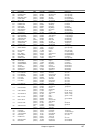
Address(H) Size(H) Data(H) Parameter Description Default Value(H)
10 0p 00 00 00 40 00-1F Displayed
Dot Data d00 00-31 --
10 0p 01# Dot Data d01
10 0p 02# Dot Data d02
10 0p : : Dot Data :
10 0p 3F# Dot Data d63
(p:Page# p=1:Page1, p=2:Page3, p=3:Page5, p=4:Page7, p=5:Page9)
10 0p 40 00 00 40 00-1F Displayed
Dot Data d00 00-31 --
10 0p 41# Dot Data d01
10 0p 42# Dot Data d02
10 0p : Dot Data :
10 0p 7F# Dot Data d63
(p:Page# p=1:Page2, p=2:Page4, p=3:Page6, p=4:Page8, p=5:Page10)
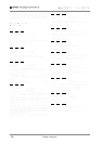
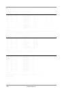
* When this message is displayed, screen data (16 x 16 dot)corresponding to the bit
pattern of the Displayed Dot Data will be stored in this unit internal memory. The
correspondence between data and dots is given below. The screen data which is
stored can be displayed by transmitting a message for address 10 20 00.
* Only in the case of Page 1, the screen data will be temporarily displayed immedi-
ately after this message is received.
bit 4 3 2 1 0 4 3 2 1 0 4 3 2 1 0 4
[ * * d00 * * ] [ * * d16 * * ] [ * * d32 * * ] [d48]
[ * * d01 * * ] [ * * d17 * * ] [ * * d33 * * ] [d49]
[ * * d02 * * ] [ * * d18 * * ] [ * * d34 * * ] [d50]
[ * * d03 * * ] [ * * d19 * * ] [ * * d35 * * ] [d51]
[ * * d04 * * ] [ * * d20 * * ] [ * * d36 * * ] [d52]
[ * * d05 * * ] [ * * d21 * * ] [ * * d37 * * ] [d53]
[ * * d06 * * ] [ * * d22 * * ] [ * * d38 * * ] [d54]
[ * * d07 * * ] [ * * d23 * * ] [ * * d39 * * ] [d55]
[ * * d08 * * ] [ * * d24 * * ] [ * * d40 * * ] [d56]
[ * * d09 * * ] [ * * d25 * * ] [ * * d41 * * ] [d57]
[ * * d10 * * ] [ * * d26 * * ] [ * * d42 * * ] [d58]
[ * * d11 * * ] [ * * d27 * * ] [ * * d43 * * ] [d59]
[ * * d12 * * ] [ * * d28 * * ] [ * * d44 * * ] [d60]
[ * * d13 * * ] [ * * d29 * * ] [ * * d45 * * ] [d61]
[ * * d14 * * ] [ * * d30 * * ] [ * * d46 * * ] [d62]
[ * * d15 * * ] [ * * d31 * * ] [ * * d47 * * ] [d63]
1 2 3 4 5 6 7 8 9 10 11 12 13 14 15 16
* For example, [ * * d00 * * ] indicates the five dots in the upper left of the display.
* The bit pattern of bits 4 - 0 (lower 5 bits) of the data byte turns the dots on/off.
However in the case of d48 - d63, only bit 4 turns the dot on/off.
d00: 0--*****
d01: 0--*****
|
d47: 0--*****
d48: 0--*----
|*: dot is unlit for 0, lit for 1
d63: 0--*---- -: dot display is not affected whether this is 0 or 1
Address(H) Size(H) Data(H) Parameter Description Default Value(H)
10 20 00 00 00 01 00-0A Display Page 00:Bar Display --
01:Page1
: :
0A:Page10 --
* When this message is received, the display (page) specified by Display Page
(address 10 20 00) will be displayed for the duration of the time specified by the fol-
lowing Display Time (address 10 20 01).
10 20 01 00 00 01 00-0F Display Time 0-7.2 [sec] 06 (2.88 [sec])
Address(H)
10 00 00
Display Data
Block
Address(H)
00 00 00
20 00 00
21 00 00
22 00 00
23 00 00
24 00 00
25 00 00
26 00 00
27 00 00
40 00 00
40 10 00
41 00 00
SYSTEM
USER TONE BANK
USER DRUM SET
USER EFX
USER PATCH COMMON
USER PATCH PART
(BLOCK 01)
USER PATCH PART
(BLOCK 01)
USER PATCH PART
(BLOCK 02)
USER PATCH PART
(BLOCK 02)
PATCH PART
(BLOCK 00-0F)
DRUM SETUP
Block Address(H) Block
A
A
50 00 00
50 10 00
51 00 00
PATCH PART
(BLOCK 10-1F)
DRUM SETUP
B
B
PATCH COMMON #A
PATCH COMMON
B
Address(H)
00 00 00
20 00 00
21 00 00
22 00 00
23 00 00
24 00 00
25 00 00
26 00 00
27 00 00
50 00 00
50 10 00
51 00 00
SYSTEM
USER TONE BANK
USER DRUM SET
USER EFX
USER PATCH COMMON
USER PATCH PART
(BLOCK01)
USER PATCH PART
(BLOCK01)
USER PATCH PART
(BLOCK02)
USER PATCH PART
(BLOCK02)
PATCH PART
(BLOCK 00-0F)
DRUM SETUP
Block Address(H) Block
A
A
40 00 00
40 10 00
41 00 00
PATCH COMMON
PATCH PART
(BLOCK 10-1F)
DRUM SETUP
#B
B
B
PATCH COMMON A