


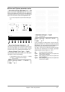
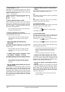
❍ LCD Contrast: 1 — 16
Depending on the angle at which this unit is placed,
the display can sometimes be difficult to read. If so,
adjust the contrast of the display. Higher values will
make the characters darker.
❍ Backup (Backup Switch): On/Off
When the power is turned off, this unit preserves
(backs up) the settings which were made, and when
the power is turned on again, these settings will reap-
pear in the display. If the Backup Switch is turned off,
the data will not be preserved.
* Even if the Backup Switch if off, the System parameter
settings (p.36) will be preserved.
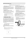
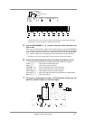
❍ IN B Sel. (IN B Select): Front/Rear
This setting determines which of the two MIDI IN B
connectors will be used. (p.135)
* After the setting of this switch is changed, the power
must be turned on once again for the new setting to
take effect.
❍ OUT/THRU (MIDI OUT/THRU Select):
OUT/THRU
This setting determines whether the rear panel MIDI
OUT/THRU connector will function as OUT or as
THRU. (p.136)
* After the setting of this switch is changed, the power
must be turned on once again for the new setting to
take effect.
❍ In Mode (Input modes): Standard, X-con-
nect, Merge → A, Merge → B, A only
This setting determines how data received at MIDI IN
A and B will be passed on to the Part Groups. (p.137)
* After the setting of this switch is changed, the power
must be turned on once again for the new setting to
take effect.
❍ Rx Sys. Mode (System Mode Set Receive
Switch): On/Off
The selection of Single Module Mode or Double
Module Mode (p.116) is called the System Mode. The
Rx Sys. Mode setting is the receive switch for MIDI
messages (System Mode Set p.194) that select the
System Mode. If Rx Sys. Mode is turned Off, the mode
will not change even if System Mode Set messages
are received. If Rx Sys. Mode is turned On, the mode
will change. (p.137)
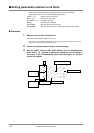
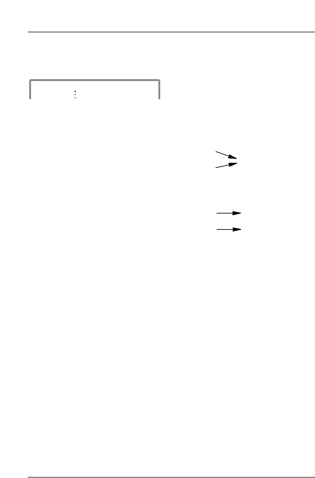
❍ Sys.OUTMode (System Output Mode) :
Sel/Fix
This determines whether the OUT Asgn (Output
Assign) setting (p.29) will be valid or not.
Sel :
The sound of each Part will be output as specified by
the OUT Asgn settings.
Fix :
The output of each Part will be fixed as follows,
regardless of the OUT Asgn settings.
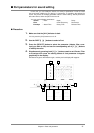
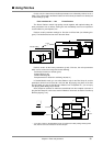
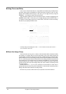
For Single Module Mode:
Both Part Group A and B will be output in stereo with
the effect sound from the Output 1 jacks.
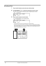
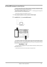
For Double Module Mode:
The Parts of group A will be output in stereo with the
effect sound from the Output 1 jacks, and the Parts of
group B similarly from the Output 2 jacks.
In this case only, the Output 2 jacks will output sound
that includes the effect sound.
* The headphone jack will output the sound that is sent to
Output 1. This means that the sound of the Parts
assigned to Output 2 will not be heard in the head-
phones.
* At the factory settings, this parameter is set to Sel.
❍ Assign Lock (Output Assign Lock): On/Off
The setting of OUT Asgn (Output Assign) (p.29) will
return to the factory settings when GS Reset or GM
System On are received. However if Assign Lock is
turned On, these settings will not change.
❍ P.Load Init (Patch Load Initialize switch):
On/Off
This specifies whether or not the settings of Parts A03
— B16 will be initialized when a Patch (p.39) is loaded.
With a setting of On, the settings of Part A03 and fol-
lowing will be initialized. With a setting of Off, the set-
tings of Part A03 and following will not be initialized.
The factory setting is On.
* In Double Module mode, the settings of Part group B
will not be initialized.
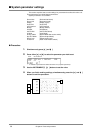
PART
INSTRUMENT
A01
100 0
LEVEL
PAN
%LCD Contrast: 8
Part Group A
Part Group B
OUTPUT 1
(Include effects)
Part Group A
Part Group B
OUTPUT 1
(Includes effects)
OUTPUT 2
(Includes effects)
Chapter 2. Parts and paramters
38