#FL Bal (Flanger balance) D> 0E - D 0<E [10]
Adjust the volume balance between the sound
which passes through the flanger and the sound
which does not. With a setting of D>0E, only the
distortion sound will be output, and with a setting of
D 0<E, the distortion sound which passes through
the flanger will be output.
“D” or “E” on the display respectively means
D(direct sound) or E(effect sound) values of 100.
Low Gain -12 - +12 [17]
Adjust the low frequency gain.
Hi Gain (High gain ) -12 - +12 [18]
Adjust the high frequency gain.
Level (Output level ) 0 - 127 [20]
Adjust the output level.
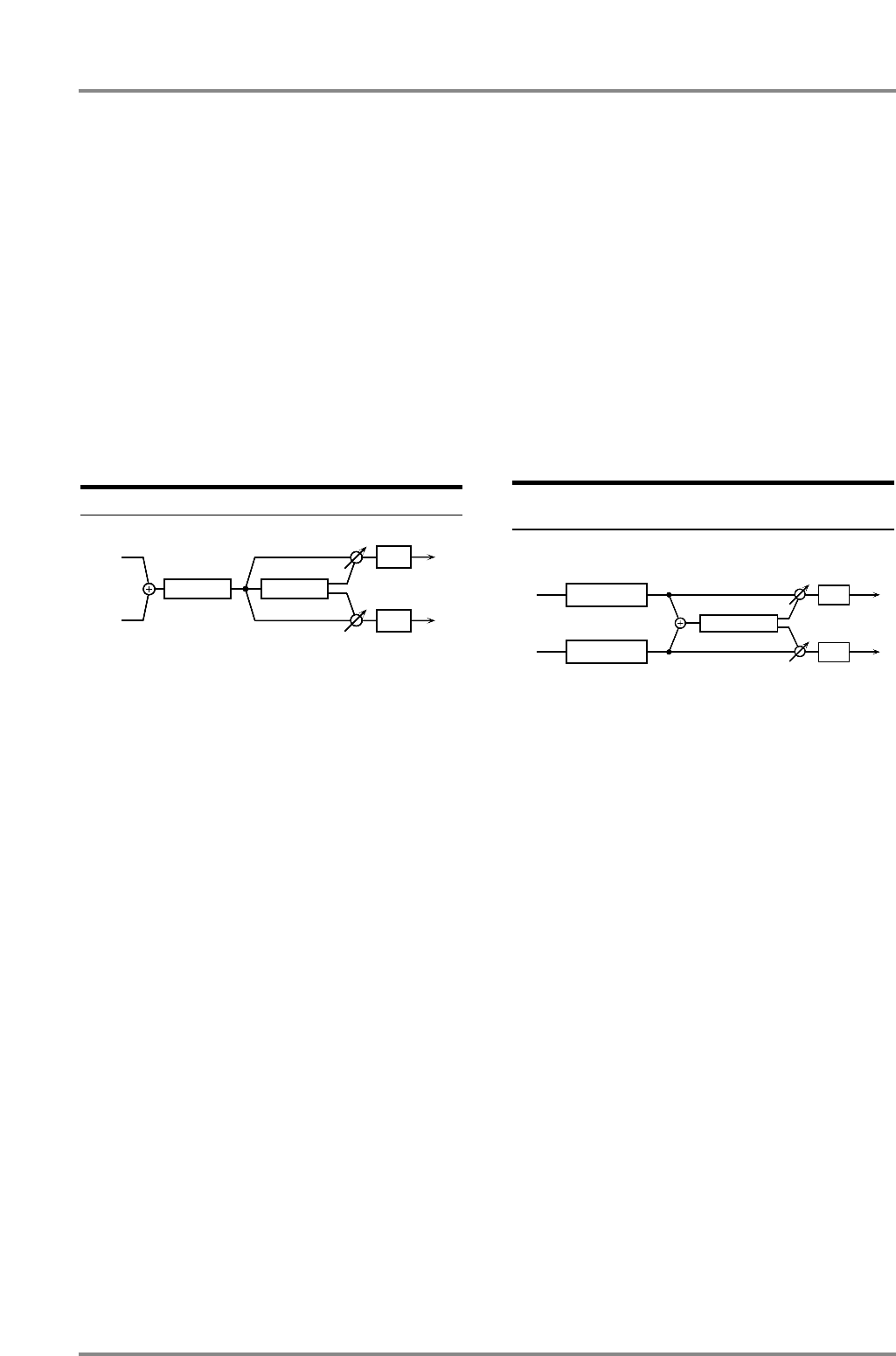
40: DS → Delay (Distortion → Delay ) [02H, 05H]
This effect connects a distortion and a delay in series.
DS Drive (Distortion drive ) 0 - 127 [1]
Adjust the degree of distortion. The volume will
change together with the degree of distortion.
+DS Pan (Distortion output pan )
L63 - 0 - R63 [2]
Adjust the stereo location of the distortion sound.
L63 is far left, 0 is center, and R63 is far right.
DS Amp (Distortion Amp Simulator Type)
Small/BltIn/2-Stk/3-Stk [3]
Select the type of guitar amp.
Small : small amp
BltIn : single-unit type amp
2-Stk : large double stack amp
3-Stk : large triple stack amp
DS Amp Sw (Distortion Amp Switch) Off/On [4]
Turn DS Amp on/off.
Dly Time (Delay time ) 0 - 500m [6]
Adjust the time delay from when the direct sound
begins until the delay sound is heard.
Dly Fb (Delay feedback level ) -98% - +98% [7]
Adjust the proportion (%) of the delay sound that is
fed back into the effect. Negative (-) settings will
invert the phase.
Dly HF (Delay HF damp ) 315 - 8k/Bypass [8]
Adjust the frequency above which delayed sound
fed back to the effect will be cut. If you do not wish
to cut the high frequencies of the feedback, set this
parameter to Bypass.
#Dly Bal (Delay balance ) D> 0E - D 0<E [10]
Adjust the volume balance between the sound
which passes through the delay and the sound
which does not. With a setting of D>0E, only the
distortion sound will be output, and with a setting of
D 0<E, the distortion sound which passes through
the delay will be output. “D” and “E” respectively
indicate D (dry sound) and E (effect sound) values
of 100.
Low Gain -12 - +12 [17]
Adjust the low frequency gain.
Hi Gain (High gain ) -12 - +12 [18]
Adjust the high frequency gain.
Level (Output level ) 0 - 127 [20]
Adjust the output level.
41: EH → Chorus (Enhancer → Chorus)
[02H, 06H]
This effect connects an enhancer and a chorus in
series.
+EH Sens (Enhancer Sensitivity ) 0 - 127 [1]
Adjust the sensitivity of the enhancer.
EH Mix (Enhancer Mix level ) 0 - 127 [2]
Adjust the ratio with which the overtones generated
by the enhancer are combined with the direct
sound.
Cho Dly (Chorus pre delay ) 0 - 100m [6]
Adjust the time delay from when the direct sound
begins until the chorus sound is heard.
Cho Rate (Chorus rate ) 0.05 - 10.0 [7]
Adjust the modulation speed of the chorus effect.
Cho Depth (Chorus depth ) 0 - 127 [8]
Adjust the modulation depth of the chorus effect.
#Cho Bal (Chorus balance ) D> 0E - D 0<E [10]
Adjust the volume balance between the sound
which passes through the chorus and the sound
which does not. With a setting of D>0E, only the
enhancer sound will be output, and with a setting of
D 0<E, the enhancer sound which passes through
the chorus will be output.
“D” or “E” on the display respectively means
D(direct sound) or E(effect sound) values of 100.
Low Gain -12 - +12 [17]
Adjust the low frequency gain.
L
R
Delay
Distortion
EQ
EQ
Balance
Enhancer
Enhancer
Chorus
L
R
EQ
EQ
Balance
Chapter 4. Insertion Effects
74


