


Editing a Normal Voice
MOTIF XS Owner’s Manual
120
Voice mode Song mode Pattern mode Mixing mode Master mode Utility mode File mode
Performance
mode
Sampling
mode 1
Sampling
mode 2
Reference
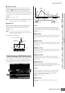
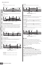
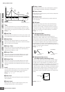
Time
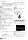
The Time parameters let you set the time between the
adjoining points of the level parameters below. A higher
value results in a longer time until reaching the next level.
Settings: 0 – 127
1 Hold Time
Determines the time between the moment you press a note
on the keyboard and the moment the envelope starts to rise.
2 Attack Time
Determines the speed of attack from the initial cutoff
frequency (Hold Level) to the maximum level of the Voice
after the hold time has elapsed.
3 Decay 1 Time
Determines how fast the envelope falls from the maximum
cutoff frequency (Attack Level) to the cutoff frequency
specified as the Decay 1 Level.
4 Decay 2 Time
Determines how fast the envelope falls from the cutoff
frequency specified as the Decay1 Level to the cutoff
frequency specified as the Decay2 Level.
5 Release Time
Determines how fast the envelope falls from the cutoff
frequency specified as the Decay2 Level to the cutoff
frequency specified as the Release Level when the note is
released.
Level
The Level parameters let you set the amount of the filter
change at each point based on the cutoff frequency
specified in the Filter Type display (page 117).
Settings: -128 – +0 – +127
6 Hold Level
Determines the initial cutoff frequency at the moment the
note is pressed.
7 Attack Level
Determines the maximum cutoff frequency which the
envelope reaches after a note is pressed.
8 Decay 1 Level
Determines the level which the cutoff frequency reaches
from the Attack Level after the Decay1 time elapses.
9 Decay 2 Level
Determines the cutoff frequency which will be maintained
while a note is held.
) Release Level
Determines the final cutoff frequency reached after the
note is released.
! EG Depth
Determines the range over which the cutoff frequency
envelope changes. A setting of 0 will cause the cutoff
frequency not to change. The farther from 0 the value is,
the larger the range of the cutoff frequency. For negative
values, the change of the cutoff frequency is reversed.
Settings: -64 – +0 – +63
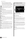
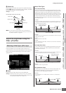
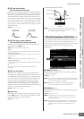
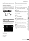
@ EG Depth Vel Sens
(EG Depth Velocity Sensitivity)
Determines how the range of the cutoff frequency
responds to velocity. When this is set to a positive value,
high velocities cause the Filter EG range to expand and
low velocities cause it to contract, as shown below. When
this is set to a negative value, high velocities cause the
Filter EG range to contract and low velocities cause it to
expand. When this is set to 0, the Filter EG range does not
change no matter what the velocity.
Settings: -64 – +0 – +63
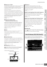
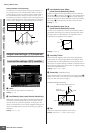
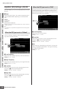
# EG Depth Vel Sens Curve
(EG Depth Velocity Sensitivity Curve)
The five curves determine how the FEG transition range
changes according to the velocity (strength) with which
you play notes on the keyboard. The selected curve is
indicated by the graphic on the display. The horizontal axis
of the graph is the velocity, and the vertical axis is the
Cutoff Frequency range. For example, the illustration below
indicates that the middle range of velocities (around 64)
causes the FEG transition range not to change and the
higher/lower range of velocities causes it to change more
greatly.
Settings: Curve 0 – 4
0
Pitch
6
Hold Level
7
Attack Level
8
Decay1
Level
9
Decay2
Level
)
Release
Level
1
Hold
Time
2
Attack
Time
3
Decay1
Time
4
Decay2
Time
5
Release
Time
Time
Pressing the key (Key on) Releasing the key (Key off)
Large range
High Velocity
Small range
Low Velocity
FEG transition
range
Velocity
High
Low
HighLow