


intJ
80386
Task gates are used to switch tasks. Task gates
may
only refer to a task state segment (see section
4.4.6 Task Switching) therefore
only the destination
selector portion of a task gate descriptor is used,
and the destination offset is ignored.
Exception
13
is
generated when a destination selec-
tor does not refer to a correct descriptor type,
i.e.,
a
code segment for
an
interrupt, trap or call gate, a
TSS
for a task gate.
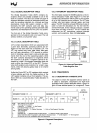
The access byte format
is
the same for all gate de-
scriptors. P = 1 indicates that the gate contents are
valid. P = 0 indicates the contents are not valid and
causes exception
11
if referenced.
DPL
is
the de-
scriptor privilege level and specifies when this de-
scriptor may be used by a task (see section 4.4
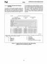
Protection). The
S field, bit 4 of the access rights
byte, must
be
0 to indicate a system control descrip-
tor. The type field specifies the descriptor type as
indicated
in
Figure 4-8.
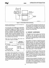
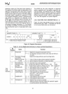
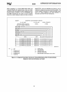
4.3.4.7
DIFFERENCES BETWEEN 386 AND 286
DESCRIPTORS
In
order to provide operating system compatibility
between the
80286 and 80386, the 386 supports all
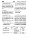
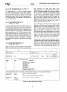
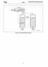
of the 80286 segment descriptors. Figure 4-9 shows
the
general format of
an
80286 system segment de-
scriptor. The only differences between 286 and 386
descriptor formats are that the
values of the type
fields, and the limit and base address fields have
been expanded for the 386. The
80286 system seg-
ment descriptors contained a 24-bit base address
and 16-bit
limit, while the 386 system segment de-
scriptors have a 32-bit base address, a 20-bit limit
field,
and a granularity bit.
By supporting
80286 system segments the 80386 is
able to execute 286 application programs
on
a
80386 operating system. This
is
possible because
the processor
automatically understands which de-
31
SEGMENT BASE
15
...
0
Intel
Reserved
Set to 0
BASE
LIMIT
P
Base Address of the segment
The
length of the segment
Present Bit 1 = Present 0 = Not Present
scriptors are 286-style descriptors and which de-
scriptors are 386-style descriptors.
In
particular, if
the upper word of a descriptor is zero, then that
de-
scriptor is a 286-style descriptor.
The
only other differences between 286-style de-
scriptors and 386 descriptors
is
the interpretation of
the word count
field of call gates and the B bit. The
word count
field specifies the number of 16-bit quan-
tities to copy for 286 call gates and 32-bit quantities
for 386
call gates. The B bit controls the size of
PUSHes when using a call gate; if B = 0 PUSHes are
16
bits, if B = 1 PUSHes are 32 bits.
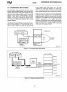
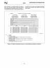
4.3.4.8
SELECTOR FIELDS
A selector
in
Protected Mode has three fields: Local
or Global Descriptor Table Indicator
(TI),
Descriptor
Entry
Index (Index), and Requestor (the selector's)
Privilege Level (RPL) as shown
in
Figure 4-10. The
TI
bits select one of two memory-based tables of
descriptors (the
Global Descriptor Table or the Local
Descriptor Table). The Index selects one of
8K
de-
scriptors
in
the appropriate descriptor table. The
RPL
bits allow high speed testing of the selector's
privilege attributes.
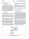
4.3.4.9
SEGMENT DESCRIPTOR CACHE
In
addition to the selector value, every segment reg-
ister has a segment descriptor cache register asso-
ciated with it. Whenever a segment register's con-
tents are changed, the 8-byte descriptor associated
with that
selector
is
automatically loaded (cached)
on the chip.
Once loaded, all references to that seg-
ment use the cached descriptor information instead
of reaccessing the descriptor. The contents of the
descriptor cache are not
visible to the programmer.
Since descriptor caches only change when a seg-
ment register
is
changed, programs which modify
the descriptor
tables must reload the appropriate
segment registers after changing a descriptor's
val-
ue.
SEGMENT LIMIT 15
...
0
P \
DPL
lsi
TYPE
\
BASE
23
...
16
DPL
S
TYPE
..
DeSCriptor PnVllege Level
0-3
System Descriptor 0 = System 1 = User
Type
of
Segment
o
o
+4
Figure 4-9. 286 Code and Data Segment
Descriptors
40