


inter
80386
TS (Task Switched, bit
3)
TS
is
automatically set whenever a task switch
operation is performed.
If
TS
is set, a coproces-
sor
ESCape opcode will cause a Coprocessor
Not
Available trap (exception
7).
The trap han-
dier typically saves the
80287/80387
context
belonging to a previous task,
loads the
80287/80387
state belonging to the current
task, and clears the
TS
bit before returning to
the faulting coprocessor opcode.
EM
(Emulate Coprocessor, bit
2)
The EMulate coprocessor bit
is
set to cause all
coprocessor opcodes to generate a Coproces-
sor Not Available
fault (exception
7).
It
is
reset
to
allow coprocessor opcodes to be executed
on
an
actual 80287 or 80387 coprocessor (this
the default case after reset). Note that the
WAIT opcode
is
not affected by the
EM
bit set-
ting.
MP
(Monitor Coprocessor, bit
1)
The
MP
bit
is
used
in
conjunction with the
TS
bit to determine if the WAIT opcode will gener-
ate a Coprocessor Not Available fault (excep-
tion
7)
when
TS
=
1.
When both
MP
= 1 and
TS =
1,
the WAIT opcode generates a trap.
Otherwise, the
WAIT opcode does not gener-
ate a trap. Note that
TS
is automatically set
whenever a task switch operation is performed.
PE
(Protection Enable, bit
0)
The
PE
bit
is
set to enable the Protected Mode.
If
PE
is
reset, the processor operates again
in
Real Mode.
PE
may
be
set
by
loading MSW or
CRO.
PE
can be reset only by a load into
CRO.
Resetting the
PE
bit
is
typically part of a longer
instruction sequence needed for proper
tran-
sition from Protected Mode to Real Mode. Note
that for strict 80286 compatibility,
PE
cannot
be
reset by the LMSW instruction.
CR1: reserved
CR1
is
reserved for use
in
future Intel processors.
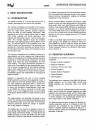
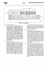
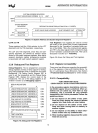
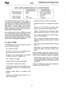
CR2: Page
Fault Linear
Address
CR2,
shown
in
Figure 2-6, holds the 32-bit linear ad-
dress that caused the last page fault detected. The
error code pushed onto the
page.
fault handler's
stack when it is invoked provides additional status
information
on
this page fault.
CR3: Page
Directory
Base
Address
CR3,
shown
in
Figure 2-6, contains the physical
base address of the page directory table. The 80386
page directory
table is always page-aligned
(4
Kbyte-aligned). Therefore the lowest twelve bits
of
CR3
are ignored when written and they store as
undefined.
A task switch through a
TSS
which changes the
value
in
CR3, or
an
explicit load into CR3 with any
value, will
invalidate all cached page table entries
in
the paging unit cache. Note that if the value
in
CR3
does not change during the task switch, the cached
page
table entries are not flushed.
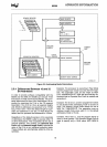
2.3.7 System Address Registers
Four special registers are defined to reference the
tables or segments supported
by
the
80286/80386
protection model. These tables or segments are:
GDT
(Global Descriptor Table),
IDT (Interrupt Descriptor Table),
LDT (Local Descriptor Table),
TSS (Task State Segment).
The addresses of these tables and segments are
stored
in
special registers, the System Address and
System Segment Registers illustrated
in
Figure 2-7.
These registers are named GDTR,
IDTR, LDTR and
TR,
respectively. Section 4 Protected Mode Archi-
tecture
describes the use of these registers.
GDTR and
IDTR
These registers hold the 32-bit linear base address
and 16-bit
limit of the GDT and
IDT,
respectively.
The GDT and
IDT segments, since they are global to
all tasks
in
the system, are defined by 32-bit linear
addresses (subject to page translation if paging is
enabled) and 16-bit
limit values.
31
24 23 16 15 8 7
o
PAGE
FAULT LINEAR ADDRESS REGISTER CR2
r--------------------------------------.~~_r_r~~~r_~_._4
PAGE
DIRECTORY BASE REGISTER
00
0 CR3
NOTE:
I·
.0:1
indicates Intel reserved:
Do
not define;
SEE
SECTION 2.3.10
Figure 2-6. Control Registers 2 and 3
12