


80386
4.5.4 Translation
Lookaside
Buffer
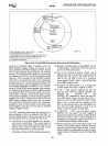
The 80386 paging hardware
is
designed to support
demand paged virtual memory systems. However,
performance would degrade
substantially if the proc-
essor was required to access two levels of tables for
every memory reference. To solve this problem, the
80386 keeps a cache of the most recently accessed
pages, this cache
is
called the Translation Looka-
side Buffer (TLB). The TLB
is
a four-way set associa-
tive 32-entry page table cache.
It automatically
keeps the most commonly used Page Table Entries
in
the processor. The 32-entry TLB coupled with a
4K page size, results
in
coverage of 128K bytes of
memory addresses. For many common multi-tasking
systems, the TLB
will have a hit rate of about 98%.
This means that the processor
will only have to ac-
cess the two-level page structure
on
2% of all mem-
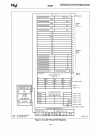
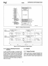
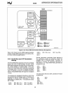
ory references. Figure 4-22 illustrates how the TLB
complements the 80386's paging mechanism.
4.5.5 Paging Operation
32
ENTRIES
PHYSICAL
~EMORY
TRANSLATION
A~~~~~S
--+-
LODKASIOE
BUFFER
HIT
MISS
31 0
U
t--
4
PAGE
PAGE
DIRECTORY
TABLE
098%
HIT
RATE
231630-68
Figure 4-22. Translation
Lookaside
Buffer
The paging hardware operates
in
the following fash·
ion. The paging unit hardware receives a 32-bit lin-
ear address from the segmentation unit. The upper
20
linear address bits are compared with all
32
en-
tries
in
the TLB to determine if there
is
a match.
If
there
is
a match
(Le.
a TLB hit), then the 32-bit phys·
ical address
is
calculated and will be placed
on
the
address
bus.
However, if the page table entry
is
not in the TLB,
the
80386 will read the appropriate Page Directory
54
Entry. If P = 1
on
the Page Directory Entry indicat-
ing that the page table
is
in
memory, then the 80386
will
read the appropriate Page Table Entry and set
the Access bit.
If P = 1 on the Page Table Entry
indicating that the page
is
in
memory, the 80386 will
update the Access and Dirty bits as needed and
fetch the operand. The upper
20
bits of the linear
address, read from the page
table, will be stored in
the TLB for future accesses. However, if P
= 0 for
either the Page Directory Entry or the
Page
Table
Entry, then the processor will generate a page fault,
an
Exception
14.
The processor will also generate
an
exception 14,
page fault, if the memory reference violated the
page protection attributes
(Le.
U/S
or R/W) (e.g. try-
ing
to write to a read-only page). CR2 will hold the
linear address which caused the page fault.
Since
Exception
14
is
classified
as
a fault,
CS:
EIP
will
point to the instruction causing the page fault. The
16-bit error code pushed
as
part of the page fault
handler
will contain status bits which indicate the
cause of the page fault.
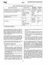
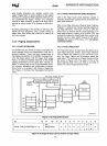
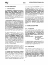
The 16-bit error code
is
used
by
the operating sys-
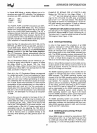
tem to determine how to handle the page fault Fig-
ure 4-23A shows the format of the page-fault error
code
and
the interpretation of the bits.
NOTE:
Even though the bits in the error code (U/S,
W/R,
and
P)
have similar names as the bits
in
the Page
Directory/Table Entries, the interpretation of the er-
ror code bits
is
different. Figure 4-23B indicates
what type of access caused the page fault.
15 3 2 1 0
lulululululululululululululul~I:lpl
Figure 4-23A. Page Fault
Error
Code
Format
U/S: The
UlS
bit indicates whether the access
causing the fault occurred when the processor was
executing
in
User Mode
(U/S
=
1)
or
in
Supervisor
mode
(U/S =
0)
W/R: The
W/R
bit indicates whether the access
causing the fault was a Read (W/R
=
0)
or a Write
(W/R
=
1)
P:
The P bit indicates whether a page fault was
caused
by
a not-present page
(P
=
0),
or
by
a page
level protection violation
(P
= 1)
U:
UNDEFINED