


HARDWARE IMPLEMENTATION
pass through the page unit unaltered. When
paging
is
enabled, the page unit translates linear
addresses to physical addresses, and verifies that
accesses are consistent with page attributes. The
page unit includes a 32-entry
translation look-
aside buffer
(TLB)
that
caches the translation
information for the most recently used pages.
Using the TLB, the page unit can translate most
page accesses (typically 98-99%) without con-
sulting the memory-based page tables. When
necessary, the page unit initiates the bus cycles
required
to
return
an
older
TLB
entry to
its
page
table and
to
load the vacated TLB slot with the
page table entry referenced by the current instruc-
tion.
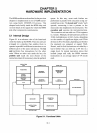
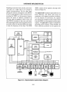
5.2 External Interface
Figure 5-2
is
a block diagram showing the 80386
in a representative system,
an
engineering work-
2X
CLOCK
DATA BUS
PROCESSOR
STATUS
AND
CONTROL
[
COPROCESSOB
[
CONTROL
A
~
CLK2
•
l\,
00-031
v'
HOLD
•
HLDA
INTR
..
NMI
..
80386
RESET
•
PEREa
•
BUSY
..
ERROR
..
station.
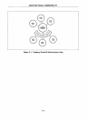
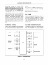
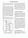
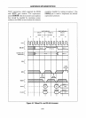
Figure
5-3
shows the 80386 external interface
in
more detail, grouping the pins into functionally
related clusters. The next sections describe the
signals associated with these pins.
5.2.1
Clock
The first versions of the 80386 run
at
12.5
or
16
MHz
and are driven by a Clock (CLK2) signal
that
is
twice the frequency of the chip. An 82384
Clock Generator provides the CLK 2 signal,
which the
80386 divides
in
two to obtain its
internal clock.
5.2.2 Data and Address Buses
The 80386 has separate 32-bit address and data
buses.
For
compatibility with existing hardware
4
Vee
GND
A2-A31
BEO-BE3
ADS
W/R
DIG
Milo
LOCK
-
NA
4
BS16
..
READY
4
~
~
V
] POWER
CONNECTIONS
BUS CYCLE
DEFINITION
Figure 5-3. Functional Pinout
5-3