


80386
cal space of the machine, 4 Gbytes
(2
32
bytes).
In
Real Address Mode, the maximum segment size is
fixed at 64 Kbytes
(2
16
bytes).
The six segments
addressable at any given moment
are defined by the segment registers
CS,
SS,
OS,
ES,
FS
and
GS.
The selector
in
CS
indicates the
current code segment; the
selector
in
SS
indicates
the current stack segment; the
selectors
in
OS,
ES,
FS
and
GS
indicate the current data segments.
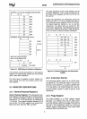
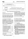
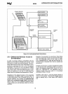
2.3.5 Segment Descriptor Registers
The segment descriptor registers are not program-
mer visible, yet it is very useful to understand their
content.
Inside the 80386, a descriptor register (pro-
grammer invisible) is associated with each program-
mer-visible
segment register, as shown
by
Figure
2-
4.
Each descriptor register holds a 32-bit segment
base address, a
32-bit segment limit, and the other
necessary segment attributes.
When a
selector value
is
loaded into a segment reg-
ister, the associated descriptor register is automati-
cally updated with the correct information.
In
Real
Address Mode, only the base address is updated
directly
(by
shifting the selector value four bits to the
left), since the segment maximum limit and attributes
are fixed
in
Real Mode.
In
Protected Mode, the base
address, the
limit, and the attributes are all updated
per the contents of the segment descriptor indexed
by the
selector.
Whenever a memory reference occurs, the segment
descriptor register associated with the segment
be-
ing used
is
automatically involved with the memory
reference. The
32-bit segment base address be-
comes a component of the linear address calcula-
tion, the 32-bit limit
is
used for the limit-check opera-
tion, and the attributes are checked against the type
of memory reference requested.
2.3.6 Control Registers
The 80386 has three control registers of 32 bits,
CRO,
CR2 and CR3, to hold machine state of a glob-
al
nature (not specific to
an
individual task). These
registers,
along with System Address Registers de-
scribed
in
the next section, hold machine state that
affects
all tasks
in
the system.
To
access the Con-
trol
Registers, load and store instructions are de-
fined.
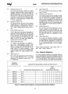
CRO:
Machine
Control
Register (includes 80286
Machine Status Word)
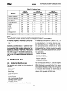
CRO,
shown
in
Figure
2-5,
contains 6 defined bits for
control and status purposes. The low-order 16 bits
of
CRO
are also known as the Machine Status Word,
MSW,
for compatibility with 80286 Protected Mode.
LMSW and SMSW instructions
are
taken as special
aliases
of the load and store
CRO
operations, where
only the low-order 16 bits of
CRO
are involved. For
compatibility with 80286 operating systems the
80386's LMSW instructions work
in
an
identical
fashion to the LMSW instruction on the 80286.
(Le.
It
only
operates
on
the low-order l6-bits of
CRO
and it
ignores the new bits
in
CRO.)
New 80386 operating
systems
should use the
MOV
CRO,
Reg
instruction.
The defined
CRO
bits are described below.
PG
(Paging Enable, bit
31)
the
PG
bit is set to enable the on-chip paging
unit.
It is reset to disable the on-chip paging
unit.
ET
(Processor Extension Type, bit 4)
ET
indicates the processor extension type (ei-
ther 80287 or 80387) as detected by the level
of the ERROR# input following 80386 reset.
The
ET
bit may also be set or reset by loading
CRO
under program control if desired. If
ET
is
set, the
80387-compatible 32-bit protocol is
used.
If ET
is
reset, 80287-compatible 16-bit
protocol
is used.
Note that for strict
80286 compatibility, ET is
not affected
by
the
LMSW
instruction. When
the
MSW or
CRO
is
stored, bit 4 accurately re-
flects
the current state of the
ET
bit.
~~---------------y--------------~}
MSW
NOTE:
f'
:;~~\I
indicates I ntel reserved: Do not define;
SEE
SECTION 2.3.10
Figure 2-5.
Control
Register 0
11