


inter
80386
ging
divides programs into multiple uniform size
pages.
Pages bear no direct relation to the logical
structure of a program. While segment selectors can
be considered the logical "name"
of
a program
module or data structure, a page most likely corre-
sponds to only a portion of a module or data struc-
ture.
By
taking advantage of the locality of reference dis-
played by most programs, only a small number of
pages from each active task need
be
in
memory at
anyone
moment.
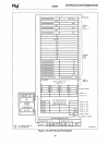
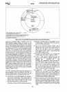
4.5.2 Paging Organization
4.5.2.1
PAGE MECHANISM
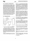
The 80386 uses two levels of tables to translate the
linear address (from the segmentation unit) into a
physical address. There
are
three components to
the paging mechanism of the 80386: the page direc-
tory, the page tables,
and
the page itself (page
frame). All memory-resident elements of the 80386
paging mechanism
are
the same
size,
namely, 4K
bytes. A uniform size for
all
of the elements simpli-
fies memory allocation and reallocation schemes,
since there is
no
problem with memory fragmenta-
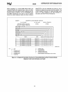
tion. Figure 4-19 shows how the paging mechanism
works.
4.5.2.2 PAGE DESCRIPTOR BASE REGISTER
CR2
is
the
Page
Fault Linear Address register. It
holds the 32-bit linear address which caused the last
page
fault detected.
CR3
is
the Page Directory Physical Base Address
Register. It contains the physical starting address of
the
Page
Directory. The lower 12 bits of
CR3
are
always zero to ensure that the
Page
Directory
is
al-
ways page aligned. Loading
it
via a
MOV
CR3,
reg
instruction causes the
Page
Table Entry cache to
be
flushed,
as
will a task switch through a
TSS
which
changes the value of
CRO.
(See 4.5.4 Translation
Lool<aside Buffer).
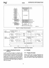
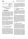
4.5.2.3 PAGE DIRECTORY
The
Page
Directory is 4K bytes long and allows
up
to
1024
Page
Directory Entries.
Each
Page
Directory
Entry contains the address of the next level of ta-
bles, the
Page
Tables and information about the
page table. The contents of a
Page
Directory Entry
are
shown
in
Figure 4-20. The upper 10 bits of the
linear address (A22-A31)
are
used
as
an
index to
select the correct Page Directory
Entry.
TWO
LEVEL
PAGING
SCHEME
31
22
12
0
~
DIRECTORY
I
TABLE
I
OFFSET
I
LINEAR
ADDRESS
10}
l
12
10
'1:
31
386
31
'r
31
0
CRO
I
f
~
CR1
PAGE
TABLE
CR2
CR3
ROOT
DIRECTORY
CONTROL
REGISTERS
Figure 4-19. Paging Mechanism
31
12
11
10 9 8 7
6 5 4
OS
PAGE
TABLE ADDRESS
31
..
12
RESERVED 0 0
D A 0
Figure 4-20. Page
Directory
Entry (POints
to
Page Table)
52
USER
MEMORY
ADDRESS
231630-67
3 2 1 0
U R
0
- -
P
S W