


80386
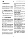
2.7.3 Segment Register Usage
The main data structure used to organize memory
is
the segment.
On
the 386, segments are variable
sized blocks of linear addresses which have certain
attributes associated with them. There are two main
types of segments: code and data, the segments are
of
variable size and can be as small as 1 byte or as
large as 4 gigabytes
(2
32
bytes).
In
order to provide compact instruction encoding,
and increase processor performance, instructions
do not need to
explicitly specify which segment reg-
ister
is
used. A default segment register
is
automati-
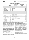
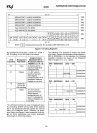
cally chosen according to the rules of Table 2-4
(Segment Register
Selection Rules).
In
general, data
references use the
selector contained
in
the
OS
reg-
ister;
Stack references use the
SS
register and In-
struction fetches use the
CS
register. The contents
of the
Instruction Pointer provides the offset. Special
segment override prefixes allow the explicit use of a
given segment register, and override the
implicit
rules listed
in Table 2-4. The override prefixes also
allow
the use of the
ES,
FS
and GS segment regis-
ters.
There are no restrictions regarding the
overlapping
of the base addresses of any segments. Thus, all 6
segments
could have the base address set to zero
and create a system with a four gigabyte
linear ad-
dress space. This creates a system where the
virtual
address space
is
the same as the linear address
space. Further
details of segmentation are dis-
cussed in section 4.1.
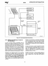
2.8 I/O SPACE
The 80386 has two distinct physical address
spaces: Memory and
1/0. Generally, peripherals are
placed in
1/0
space although the 80386 also sup-
ports memory-mapped peripherals. The
1/0
space
consists of 64K bytes, it can be divided into 64K 8-
bit ports, 32K 16-bit ports, or 16K 32-bit ports, or any
combination of ports which add up to
less than 64K
bytes. The 64K
1/0
address space refers to physical
memory rather than linear address since
1/0
instruc-
tions do not
go
through the segmentation or paging
hardware. The
M/IO#
pin acts as
an
additional ad-
dress
line thus allowing the system designer to easi-
ly
determine which address space the processor
is
accessing.
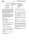
Table 2-4. Segment Register Selection Rules
Type
of
Implied (Default) Segment Override
Memory Reference
Segment Use Prefixes Possible
Code Fetch
CS
None
Destination of
PUSH,
PUSHA instructions
SS
None
Source of
POP,
POPA
instructions
SS
None
Other data references,
with effective address
using base register of:
[EAX]
OS
CS,SS,ES,FS,GS
[ESX]
OS
CS,SS,ES,FS,GS
[ECX]
OS
CS,SS,ES,FS,GS
[EOX]
OS
CS,SS,ES,FS,GS
[ESX]
OS
CS,SS,ES,FS,GS
[ESI]
OS
CS,SS,ES,FS,GS
[EOI]·
DS
CS,SS,ES,FS,GS
[ESP]
SS
CS,DS,ES,FS,GS
[ESP]
SS
CS,DS,ES,FS,GS
• Data references for the memory destination
of
the STaS and MaVS instructions (and REP STaS and REP MaVS)
use
01
as the base register and
ES
as the segment, with no override possible.
22