intJ
80386
7.5 A.C. SPECIFICATIONS
7.5.1
A.C. Spec Definitions
The
A.C.
specifications, given
in
Tables 7-4
and
7-5,
consist of output delays, input setup requirements
and input
hold requirements.
All
A.C.
specifications
are
relative to the CLK2 rising edge crossing the
2.0V
level.
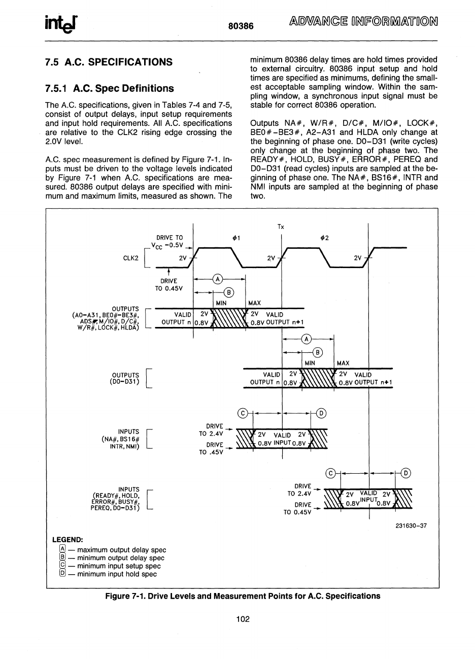
A.C.
spec measurement
is
defined by Figure 7-1.
In-
puts must be driven to the voltage levels indicated
by
Figure
7-1
when
A.C.
specifications are mea-
sured.
80386 output delays are specified with mini-
mum
and
maximum limits, measured
as
shown. The
CLK2
minimum 80386 delay times are hold times provided
to external circuitry. 80386 input setup and hold
times are specified
as
minimums, defining the small-
est acceptable sampling window. Within the sam-
pling window, a synchronous input signal must
be
stable for correct 80386 operation.
Outputs
NA#,
W/R#,
O/C#,
M/IO#,
LOCK#,
BEO#-BE3#,
A2-A31 and HLDA only change at
the beginning of phase one.
00-031
(write cycles)
only change at the beginning of phase two. The
REAOY#,
HOLO,
BU8Y#, ERROR#,
PEREQ
and
00-031
(read cycles) inputs are sampled at the be-
ginning of phase one. The
NA#,
B816#,
INTR
and
NMI
inputs
are
sampled at the beginning of phase
two.
Tx
(AO-A31,
BEO#-BE3#, VALID
OUTPUTS
[
ADSt:M/IO#.
D/C#.
J:\',\\,\\\~
O.BV
OUTPUT n+1
W/R#.
LOCK#. HLDA)
___
-+;,,;,;,.~
....
~~to.,;,,;,~_..,..
__
LEGEND:
OUTPUTS
[
(DO-D31 )
INPUTS [
(NA#.BS16#
INTR.
NMI)
INPUTS
(READY#. HOLD.
[
ERROR#.
BUSY#.
PEREa.
DO-D31)
;
- maximum output delay spec
B _ minimum output delay spec
c - minimum input setup spec
D _ minimum input hold spec
DRIVE
_
~~---+---m,""
TO
2.4V
DRIVE
TO
.45V
DRIVE
TO
2.4V
DRIVE
TO
0.45V
MAX
2V
VALID
O.BV
OUTPUT
n+1
Figure 7-1. Drive Levels and Measurement Points for
A.C.
Specifications
102
231630-37


