


80386
2.5 ADDRESSING
MODES
2.5.1
Addressing Modes Overview
The 80386 provides a total of
11
addressing modes
for instructions to specify operands. The addressing
modes are optimized to
allow the efficient execution
of high
level languages such as C and FORTRAN,
and they cover the vast majority of data references
needed by
high-level languages.
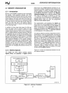
2.5.2 Register and Immediate Modes
Two of the addressing modes provide for instruc-
tions that operate
on
register or immediate oper-
ands:
Register Operand Mode: The operand is
located
in
one of the
8-,
16- or 32-bit general registers.
Immediate Operand Mode: The operand is in-
cluded
in
the instruction as part of the opcode.
2.5.3 32-Bit Memory Addressing
Modes
The remaining 9 modes provide a mechanism for
specifying the effective address of
an
operand. The
linear address consists of two components: the seg-
ment base address and
an
effective address. The
effective address
is
calculated by using combina-
tions of the
following four address elements:
DISPLACEMENT:
An
8-,
or 32-bit immediate value,
following
the instruction.
BASE: The contents of any general purpose regis-
ter. The base registers are
generally used by compil-
ers
to
point to the start of the local variable area.
INDEX: The contents of any general purpose regis-
ter except for
ESP.
The index registers are used to
access the
elements of
an
array, or a string of char-
acters.
SCALE: The index register's value can be multiplied
by
a scale factor, either
1,
2,
4 or
8.
Scaled index
mode
is
especially useful for accessing arrays or
structures.
Combinations of these
4 components make
up
the 9
additional addressing modes. There
is
no perform-
ance
penalty for using any of these addressing com-
binations, since the effective address
calculation
is
pipelined with the execution of other instructions.
17
The one exception is the simultaneous use of Base
and
Index components which requires one addition-
al
clock.
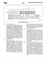
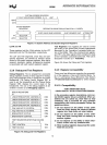
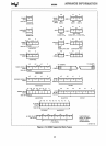
As
shown
in
Figure 2-9, the effective address
(EA)
of
an
operand is calculated according to the following
formula.
EA
= Base Reg + (Index
Reg'
Scaling) + Displacement
Direct Mode: The operand's offset is contained as
part of the instruction as
an
8-,
16- or 32-bit dis-
placement.
EXAMPLE: INC
Word
PTR [500]
Register Indirect Mode: A BASE register contains
the address of the operand.
EXAMPLE:
MOV [ECX], EDX
Based Mode: A
BASE register's contents
is
added
to
a DISPLACEMENT to form the operands offset.
EXAMPLE:
MOV ECX, [EAX + 24]
Index Mode:
An
INDEX register's contents
is
added
to a
DISPLACEMENT to form the operands offset.
EXAMPLE: ADD EAX,
TABLE[ESIl
Scaled Index
Mode:
An
INDEX register's contents is
multiplied
by
a scaling factor which
is
added to a
DISPLACEMENT to form the operands offset.
EXAMPLE:
IMUL EBX, TABLE[ESI*4],7
Based Index Mode: The contents of a BASE register
is
added to the contents of
an
INDEX register to
form the effective address of
an
operand.
EXAMPLE:
MOV EAX, [ESI] [EBX]
Based
Scaled Index Mode: The contents of an IN-
DEX
register
is
multiplied
by
a SCALING factor and
the
result
is
added to the contents of a BASE regis-
ter to obtain the operands offset.
EXAMPLE:
MOV ECX, [EDX*S] [EAX]
Based
Index Mode with Displacement: The contents
of
an
INDEX Register and a BASE register's con-
tents and a
DISPLACEMENT are all summed to-
gether to form the operand offset.
EXAMPLE: ADD EDX,
[ESIl [EBP+OOFFFFFOH]
Based Scaled Index Mode with Displacement: The
contents of
an
INDEX register are multiplied
by
a
SCALING factor, the result is added to the contents
of a
BASE register and a DISPLACEMENT to form
the operand's offset.
EXAMPLE:
MOV EAX, LOCALTABLE[EDI*4]
[EBP+SO]