


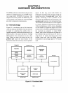


HARDWARE IMPLEMENTATION
5.2.5 Dynamic Bus Sizing
In addition to controlling the timing
of
bus cycle
definitions, the memory (and
1/0)
subsystem
can also dynamically control the effective
size
of
the data bus. Dynamic bus sizing permits:
I.
Arbitrary combinations of
16-
and 32-bit
memory subsystems; software can make 32-
bit transfers without regard to whether
it
is
accessing
16-
or
32-bit memory.
2.
Simple connection to 16-bit buses, such as the
MULTIBUS I bus.
3.
Compatibility with 16-bit peripherals (and
their drivers) whose registers are usually
located on
16-
rather than 32-bit boundaries.
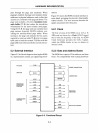
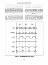
By
asserting the Bus Size
16
(BSI6) signal,
external hardware can instruct the processor to
perform the current transfer on only the
low
16
bits of the data bus. If
BS
16
is
asserted, and the
access
is
32
bits, the processor automatically runs
two bus cycles (see Figure
5-7).
The 80386
samples BS16 late in the bus cycle, permitting
external hardware to assert it only for relevant
memory and
110 addresses.
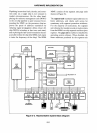
5.2.6 Processor Status and Control
Another bus master (a processor
or
an intelligent
peripheral, such as a
DMA
controller), can
request to use the
80386 local bus by asserting the
80386's HOLD signal. The processor grants the
bus
by
asserting
HLDA
(Hold Acknowledge)
at
the end
of
the current bus cycle (if any); it will
then suspend its next bus cycle until
HOLD
is
deasserted. When the 80386 relinquishes the bus
to another master,
it
drives
HLDA
active
and
three-states all other pins, electrically isolating
itself from the system.
80386 interrupts are classified as maskable
or
non-maskable; the former arrive on the pro-
cessor's INTR (Interrupt Request) pin and the
latter on its NMI (Non-maskabIe Interrupt
5-7
Request) pin. Operating system software can
make the
80386
ignore the INTR pin by clearing
the Interrupt Enable flag. The processor always
samples the NMI pin; many systems use this pin
to inform the processor of an impending power
failure
or
a major system error.
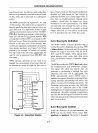
Maskable interrupt requests are usually con-
nected to
INTR
through one
or
more 8259A
Programmable Interrupt Controllers (PICs).
Each 8259A can handle up to eight interrupt
sources; multiple 8259As can be cascaded to
provide up to 64 different interrupt sources. The
operating system initializes each 8259A with
an
identifying number (vector) to supply for each
interrupt source the
PIC
monitors. The 8259A
supplies this number to the
80386 in response to
the processor's interrupt acknowledge bus cycle.
The
80386 uses the number to invoke the handler
designated to respond to the interrupt.
Asserting
RESET places the processor in a pre-
defined initial state
(in
Real
Mode with interrupts
disabled), and makes
it
fetch an instruction from
physical address
FFFFFFFOH.
5.2.7 Coprocessor Control
The 80386 passes instructions and operands to
an
80287
or
80387 Numeric Coprocessor by
running
110 bus cycles to reserved addresses
above the normal
64
kilobyte 110 space. A
numeric coprocessor can be selected by
A31
high
and
MilO
low.
The 80386 uses different com-
munication protocols for each coprocessor, pass-
ing 16-bit quantities to the
80287 and 32-bit
quantities to the
80387.
The 80386 can tell when
it
is
RESET
if
an
80387
is
present; system initiali-
zation software can check for the presence
of
an
80287.
The coprocessor asserts BUSY while
it
is
exe-
cuting an instruction. The
80386 does not pass
the next numeric instruction to the coprocessor
until
BUSY
is
negated. Software can synchronize
the
80386 with a coprocessor by issuing the