


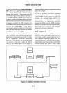

SYSTEM ARCHITECTURE
the new task's Instruction Pointer.
To
later
resume execution
of
the old task, the operating
system issues a
Jump
TSS to the old task's TSS;
execution
of
the old task then continues with the
instruction following the
Jump
TSS that sus-
pended the task.
The
task switch described here
takes
17
microseconds
(16
M Hz., no wait states).
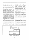
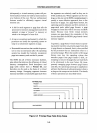
3.3 Addressing
The physical address space
of
most computers
is
organized as a simple array
of
bytes. With the
development
of
memory management units
(M
MUs), computer architectures began to distin-
guish between the physical address space imple-
mented by the memory hardware and the logical
address space seen
by
a programmer. The M M U
translates the logical addresses presented by
programs into the physical addresses that go
out
on the bus. Most architectures view a task's
logical address space as consisting
of
a collection
of
one
of
the following:
Bytes
Segments
Pages
The logical address space con-
sists of
an
array
of
bytes with
no other structure (this
is
some-
times called a
"flat"
or
"linear"
address
space).
NoM
M U trans-
lation
is
required because a
logical address
is
exactly equiv-
alent to a physical address.
The logical address space con-
sists of a
few
or
many segments,
each
of
which
is
composed
of
a variable number
of
bytes. A
logical address
is
given in two
parts, a segment number and
an
offset into the segment. The
MMU
translates a logical ad-
dress into a physical address.
The logical address space con-
sists
of
many pages, each
of
which
is
composed
of
a fixed
number
of
bytes. A logical
address
is
a page number plus
3-3
an
offset within the page. The
MMU
translates a logical ad-
dress into a physical address.
Paged Segments
The
logical address space con-
sists
of
segments which them-
selves
consist
of
pages. A logical
address
is
a segment number
and an offset. The
MMU trans-
lates the logical address into a
page number and
an
offset
and then translates these into
a physical address.
Each
of
these views matches some classes
of
system well and others
less
well.
For
example,
the
"flat"
view
is
appropriate for simple embedded
systems, while systems that separately manage
and protect individual program structures fit
better with the segmented view
of
memory.
Technically, the
80386 views memory as a collec-
tion
of
segments that are optionally paged. In
practice, the
80386 architecture supports operat-
ing systems that use any of the four views
of
memory described above.
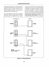
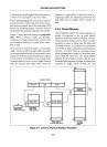
3.3.1
Address Translation Overview
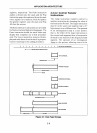
Figure
3-3
shows the fundamentals
of
80386
logical-to-physical address translation. The se-
quence
of
operations shown in Figure
3-3
is
central to both addressing and protection.
It
is
described here
in
skeleton form to clearly establish
its
overall outline before considering such features
as
virtual memory and protection. Subsequent
sections elaborate on the translation stages and
show how they can
be
tailored to fit the needs
of
a particular system.
As described in the previous chapter, the
80386
memory addressing modes yield the 32-bit offset
ofthe
target operand. Combined with a segment
selector, this offset forms a two-part logical
address: the selector identifies the target segment
and the offset locates the operand in the segment.
In the vast majority
of
instructions, the selector
is
specified implicitly as the content
of
a segment
register.