


CHAPTER 5
HARDWARE IMPLEMENTATION
The 80386 architecture described in the previous
chapters
is
implemented in over 275,000 transis-
tors using Intel's
CHMOS
III process. This
chapter looks briefly inside the
80386 chip, and
in more detail at the signals by which the
80386
and other components communicate.
5.1
Internal Design
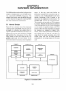
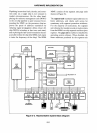
Figure
5-1
is
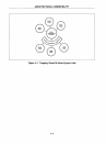
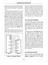
an abstract view of the functional
units that make up the
80386. These six units are
arranged in a pipeline that enables them to
operate in parallel on different instructions or on
different parts of the same instruction. The bus
unit performs bus transactions for the other
units. When no other unit needs the bus, the
prefetch unit reads the next dword of the
instruction stream from memory into the prefetch
-
EXECUTION
UNIT
REGISTERS
BARREL
SHIFTER
MULTIPLY!
DIVIDE
ALU
t
SEGMENT
UNIT
SEGMENT
REGISTERS
SEGMENT
r--
TRANSLATOR
t
I
DECODER
-
INSTRUCTION
QUEUE
queue. In this way, most code fetches are
performed in parallel with execution using un-
needed bus cycles. The decode unit
"cracks" each
opcode, converting
it
into a pointer to the
microcode that implements the instruction. The
execution unit executes the microinstructions.
The execution unit can add two 32-bit registers
in 2 clocks. Multiply/ divide hardware performs
32-bit multiplications in
9-41
clocks, depending
on the number of significant digits, and 32-bit
division in
38
or42
clocks, depending on whether
the operands are unsigned or signed. Shift,
Rotate, and bit field instructions are aided by a
barrel shifter that can shift up to
64
bits in a
single clock. In typical instruction mixes that
include jumps and calls, the
80386 executes
instructions at
an
average speed
of
4.4 clocks
each.
PAGE
UNIT
TRANSLATION
LOOKASIDE
BUFFER
PAGE
BUS
UNIT
r-
TRANSLATOR
t
BUS INTERFACE
•
PREFETCH
QUEUE
PREFETCHER
DECODE
UNIT
PREFETCH
UNIT
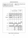
Figure
5-1.
Functional Units
5-1