


80386
the processor during a task switch, to avoid spurious
exceptions
in
the new task. Note that the break-
points must be re-enabled under software control.
All
80386
Gi
bits are unaffected during a task switch.
The
Gi
bits support breakpoints that are active
in
all
tasks executing
in
the system.
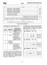
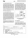
2.12.3.3 DEBUG STATUS REGISTER (DR6)
A Debug Status Register,
DR6
shown
in
Figure 2-13,
allows the exception 1 handler to easily determine
why it was invoked. Note the exception 1 handler
can be invoked
as
a result of one of several events:
1)
DRO
Breakpoint fault/trap.
2)
DR1
Breakpoint fault/trap.
3)
DR2 Breakpoint fault/trap.
4)
DR3 Breakpoint fault/trap.
5)
Single-step (TF) trap.
6)
Task switch trap.
7) Fault due to attempted debug register access
when
GD=
1.
The Debug Status Register contains single-bit flags
for each of the possible events invoking exception
1.
Note below that some of these events are faults (ex-
ception taken before the instruction
is
executed),
while other events are traps (exception taken after
the debug events occurred).
The flags
in
DR6 are set
by
the hardware but never
cleared
by
hardware. Exception 1 handler software
should clear DR6 before returning to the user pro-
gram to avoid future confusion
in
identifying the
source of exception
1.
The fields within the Debug Status Register,
DR6,
are as follows:
Bi
(debug fault/trap due to breakpoint
0-3)
Four breakpoint indicator flags, BO-B3, correspond
one-to-one with the breakpoint registers
in
DRO-
DR3.
A flag
Bi
is
set when the condition described
by
DRi,
LENi,
and
RWi
occurs.
If
Gi
or
Li
is
set, and if the ith breakpoint
is
detected,
the processor will invoke the exception 1 handler.
The exception
is
handled as a fault if
an
instruction
execution breakpoint occurred, or as a trap if a data
breakpoint occurred.
IMPORTANT NOTE: A flag
Bi
is
set whenever the
hardware detects a match condition on
enabled
breakpoint
i.
Whenever a match
is
detected
on
at
least one
enabled breakpoint
i,
the hardware imme-
diately sets all
Bi
bits corresponding to breakpoint
conditions matching at that instant, whether enabled
or
not. Therefore, the exception 1 handler may see
31
that multiple
Bi
bits are set, but only set
Bi
bits corre-
sponding to
enabled breakpoints (Li or
Gi
set) are
true indications of why the exception 1 handler was
invoked.
BD
(debug fault due to attempted register access
when
GD
bit set)
This bit
is
set if the exception 1 handler was invoked
due to
an
instruction attempting to read or write to
the debug registers when
GD
bit was set.
If
such
an
event occurs, then the
GD
bit
is
automatically
cleared when the exception 1 handler
is
invoked,
allowing handler access to the debug registers.
BS
(debug trap due to single-step)
This bit
is
set if the exception 1 handler was invoked
due to the TF bit
in
the flag register being set (for
single-stepping).
See section 2.12.2.
BT
(debug trap due to task switch)
This bit
is
set if the exception 1 handler was invoked
due to a task switch occurring to a task having a 386
TSS with the T bit set. (See Figure 4-15a). Note the
task switch into the new task occurs normally, but
before the first instruction of the task
is
executed,
the exception 1 handler
is
invoked. With respect to
the task switch operation, the operation
is
consid-
ered to
be
a trap.
2.12.3.4 USE OF RESUME FLAG (RF)
IN
FLAG
REGISTER
The Resume Flag (RF)
in
the flag word can sup-
press
an
instruction execution breakpoint when the
exception 1 handler returns to a user program at a
user address which
is
also
an
instruction execution
breakpoint.
See section 2.3.3.
3.
REAL MODE ARCHITECTURE
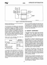
3.1
REAL MODE INTRODUCTION
When the processor
is
reset or powered up it
is
ini-
tialized
in
Real Mode. Real Mode has the same base
architecture as the
8086, but allows access to the
32-bit register set of the
80386. The addressing
mechanism, memory size, interrupt handling, are all
identical to the Real Mode
on
the 80286.
All of the 80386 instructions are available in Real
Mode (except those instructions listed in 4.6.4). The
default operand size
in
Real Mode
is
16-bits, just like
the
8086.
In
order to use the 32-bit registers and
addressing modes, override prefixes must be used.
In
addition, the segment size
on
the 80386
in
Real
Mode
is
64K bytes so 32-bit effective addresses
must have a value less the
OOOOFFFFH.
The primary