


inter
80386
0;-
r:-
~
;;;-
N
0;-
r:-
"' "'
'"
<J)
0
...
OJ
'\
'"
...
~
OJ
I')
OJ
.,;
.,;
C
~
e
e
c c
c
C
IN
#l
POSITION
2
3
4
5
6
7
•
®00®00'10000000
®00®0000000000
o ®
~
0 0 ®
®'0
0 0 0
~
0 0
000
00®
®®0
®00
0®0
I
®00
0®0
+
00®
B -0 0 @ -- - - ® 0 ®
9
10
11
12
13
14
00® 0®0
0®®
0®®
®®0
000
o ® e
0000,0000
00
o ® ® 0 ® 0
010
®
0@0
0 0
® ® ® 0 ® ®
®,®@@@@®®
0
...
<Xi
c
L()
'"
r-:
M
.O~O
':....1_
ABC
D E F G H J K L
.020
(0.508)
MIN
TYP
-
.070
(1.777)
DIA
TYP
BRAZE
PAD
(0.508)
1------
1.450
(36.802)
-------1
.725
(18.401)
.650
(16.497)
.550
(13.959)
.450
(11.421)
.350
(8.883)
.250
(6.345)
.150
(3.807)
.050
(1.269)
o
SWEDGE
PIN
STANDOFF
(4)
PLACES
.057(1.269)
-1
1
-
MAX
TYP
.001
(0.025)
R
MIN
TYP
.018
(0.47)
1
DIA
TYP
-
=~1If
.165(4'189~1
~
.110(2:J-j
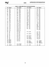
231630-35
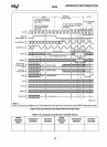
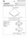
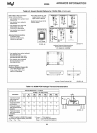
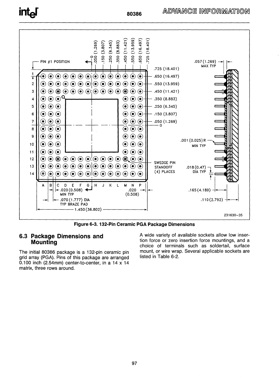
Figure 6-3. 132-Pin Ceramic PGA Package Dimensions
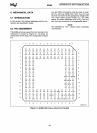
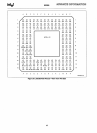
6.3 Package Dimensions and
Mounting
The initial 80386 package is a 132-pin ceramic
pin
grid array (PGA). Pins of this package are arranged
0.100 inch (2.54mm) center·to·center,
in
a
14
x 14
matrix, three rows around.
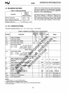
97
A wide variety of available sockets allow low inser-
tion force or zero insertion force mountings, and a
choice of
terminals such
as
soldertail, surface
mount, or wire wrap.
Several applicable sockets are
listed
in
Table 6·2.