


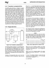
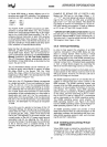
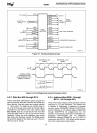
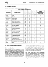

80386
2X
CLOCK
[
32-BIT[DO_D31
DATA
BUS
[
CONTROL
BUS{
ARBITRATION
INTERRUPTS
{
CLK2
~
<
DATA
BUS
~
v
ADS#
R~~~:
~
80386
PROCESSOR
HOLD
~
HLDA
INTR
t>
NMI
t>
RESET
t>
ADDRESS
BUS
BE3#
BE2#
BE1#
BEO#
W/R#
D/C#
M/IO#
LOCK#
PEREQ
I~
BUSY#
~
ERROR#
Vee
<l
GND
<l
t\
v
A2-A31
1
BYTE
ENABLES
32-BIT
ADDRESS
}
COPROCESSOR
SIGNALLING
}
POWER
CONNECTIONS
231630-1
Figure 5-1. Functional Signal
Groups
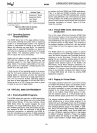
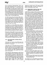
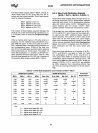
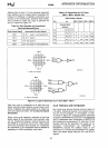
PROCESSOR
CLOCK
PERIOD
PROCESSOR
CLOCK
PERIOD
CLK2
PERIOD
CLK2
PERIOD
CLK2
PERIOD
CLK2
PERIOD
~1
~2
~1
~2
CLK2
[
INTERNAL
80386
PROCESSOR
CLOCK
[
(SAME
FREQUENCY
AS
82384
CLK
SIGNAL)
62 ns MIN}
(16
MHz
MAX)
80386-16
83
ns
MIN}
(12.5
MHz
MAX)
80386-12
231630-2
Figure 5-2. CLK2 Signal and Internal
Processor
Clock
5.2.3 Data Bus
(DO
through
031)
These three-state bidirectional signals provide the
general purpose data path between the
80386 and
other devices. Data bus inputs and outputs indicate
"1"
when HIGH. The data bus can transfer data
on
32-
and
16-bit buses using a data bus sizing feature
controlled
by
the
8S16#
input. See section 5.2.6
Bus
Conto!. Data bus reads require that read data
setup
and
hold times
t21
and
t22
be met for correct
operation. During any write operation (and during
halt cycles and shutdown cycles), the
80386 always
drives all 32 signals of the data bus even if the
cur-
rent bus size
is
16-bits.
61
5.2.4
Address
Bus (BEO#
through
BE3#,
A2
through
A31)
These three-state outputs provide physical memory
addresses or
I/O
port addresses. The address bus
is
capable of addressing 4 gigabytes of physical
memory space
(OOOOOOOOH
through FFFFFFFFH),
and
64
kilobytes of
I/O
address space
(OOOOOOOOH
through
OOOOFFFFH)
for programmed I/O.
I/O
transfers automatically generated for 80386-to-co-
processor communication use
I/O
addresses
800000F8H through 800000FFH,
so
A31
HIGH
in
conjunction with
M/IO#
LOW
allows simple genera-
tion of the coprocessor select signal.