


intJ
80386
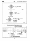
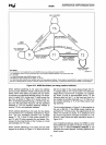
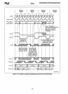
HOLD
ASSERTED
REQUEST
PENDING.
HOLD
NEGATED
Bus States:
ALWAYS
READY#
ASSERTED'
HOLD NEGATED'
REQUEST
PENDING
READY#
NEGATED'
NA#
NEGATED
Tl-first
clock of a non-pipelined bus cycle (80386 drives new address and asserts
ADS#)
T2-subsequent
clocks
of
a bus cycle when
NA
# has not been sampled asserted in the current bus cycle
231630-17
Ti-
idle state
Th-hold
acknowledge state (80386 asserts HLDA)
The fastest bus
cycle consists
of
two states:
Tl
and T2.
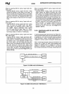
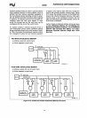
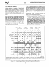
Four basic bus states describe bus operation when not using pipelined address. These states do include
8S16 # usage for 32-bit and 16-bit
bus size.
If asserting
8S16#
requires a second 16-bit bus cycle to be performed, it is performed before HOLD asserted is acknowledged.
Figure
5-13_
80386 Bus States
(not
usIng pipelined address)
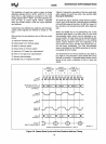
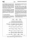
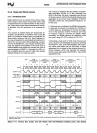
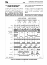
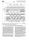
When address
pipelining is not used, the address
and bus
cycle definition remain valid during all wait
states. When wait states are added and
you
desire
to maintain
non-pipelined address timing, it
is
neces-
sary to negate
NA#
during each T2 state except the
last one, as shown
in
Figure 5-12 cycles 2 and
3.
If
NA#
is
sampled asserted during a T2 other than the
last one, the next state would be
T21
(for pipe lined
address) or T2P (for pipelined address) instead of
another T2 (for
non-pipelined address).
When address
pipelining is not used, the bus states
and transitions are
completely illustrated by Figure
5-13. The bus transitions between four
possible
states: T1, T2, Ti, and Th. Bus cycles consist of
T1
and T2, with T2 being repeated for wait states. Oth-
erwise, the bus may be idle,
in
the Ti state, or
in
hold
acknowledge,
the Th state.
When address
pipelining is not used, the bus state
diagram is as shown
in
Figure 5-13. When the bus
is
77
idle it is
in
state Ti. Bus cycles always begin with T1.
T1
always leads to T2. If a bus cycle is not acknowl-
edged during T2 and
NA#
is negated, T2 is repeat-
ed.
When a cycle is acknowledged during T2, the
following state will be
T1
of the next bus cycle if a
bus request is pending
internally, or Ti if there
is
no
bus request pending, or Th if the
HOLD input is be-
ing
asserted.
The bus state diagram
in
Figure 5-13 also applies to
the use of
B516#.
If the
B03B6
makes internal ad-
justments for 16-bit bus size, the adjustments do not
affect the
external bus states. If an additional 16-bit
bus
cycle is required to complete a transfer on a 16-
bit bus, it
also follows the state transitions shown
in
Figure 5-13.
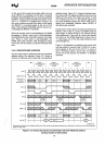
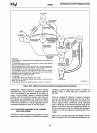
Use of pipe
lined address allows the 803B6 to enter
three
additional bus states not shown in Figure 5-13.
Figure 5-20
in
5.4.3.4 Pipelined
Address
is the
complete bus state diagram, including pipelined ad-
dress cycles.