


inter
80386
5.4.3 Read and Write Cycles
5.4.3.1
INTRODUCTION
Data transfers occur
as
a result of bus cycles, classi-
fied
as
read or write cycles. During read cycles, data
is
transferred from
an
external device to the proces-
sor. During write
cycles data
is
transferred
in
the oth-
er direction, from the processor to
an
external de-
vice.
Two choices of address timing are
dynamically se-
lectable:
non-pipe lined, or pipe lined. After a bus idle
state, the processor always uses non-pipelined
~d
dress timing. However, the
NA#
(Next Address)
in-
put
may
be asserted to select pipelined address tim-
ing
for the next bus cycle. When pipelining
is
select-
ed and the 80386 has a bus request pending inter-
nally, the address and definition of the next cycle
!s
made available even before the current bus cycle IS
acknowledged by READY#. Generally, the
NA#
in-
put
is
sampled each bus cycle to select the desired
address timing for the next bus
cycle.
Two choices of physical data bus width are dynami-
cally selectable:
32
bits, or 16 bits. Generally, the
B816#
(Bus 8ize
16)
input
is
sampled near the end
of the bus
cycle to confirm the physical data bus size
applicable to the current cycle. Negation of
B816#
indicates a 32-bit
size,
and assertion indicates a 16-
bit bus size.
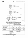
If 16-bit bus size
is
indicated, the 80386 automatical-
ly
responds
as
required to complete the transfer on
a 16-bit data
bus.
Depending on the size and align-
ment of the operand, another 16-bit bus cycle may
be
required. Table
5-7
provides all details. When
necessary, the
80386 performs
an
additional 16-bit
bus
cycle, using
00-015
in
place of
016-031.
Terminating a read cycle or write cycle, like any bus
cycle, requires acknowledging the cycle
by
asserting
the READY # input. Until
acknowledged, the proces-
sor inserts wait states into the bus
cycle, to allow
adjustment for the speed of any external device.
Ex-
ternal hardware, which has decoded the address
and bus
cycle type asserts the READY # input at the
appropriate time.
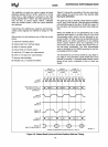
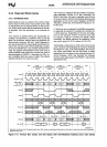
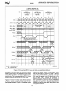
IDLE
[
CYCLE
1
NON-PIPELINED
(WRITE)
CYCLE
2 [
NON-PIPELINED
(READ)
CYCLE
3
[IDLE
[
CYCLE
4
[IDLE
[
NON-PIPELINED NON-PIPELINED
(WRITE)
(READ)
ClK2
[
(82384
ClK)
[
BED
#-BE3 # [
A2-
A31,
M/IO#,O/C#
Ti
W/R#
[
~~9'
ADS# [
READY
# [
00-
031 [
T1
T2
T1
T2
T1
T2
Ti
T1
T2
Ti
231630-15
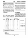
Idle states are shown here for diagram variety only. Write cycles are not always fallowed by an idle state. An active bus cycle can immediately
follow
the write cycle.
Figure 5-11. Various
Bus
Cycles and Idle States with Non-Pipelined Address (zero wait states)
75