


80386
2.7 MEMORY ORGANIZATION
2.7.1 Introduction
~emory
on the 80386
is
divided
up
into 8-bit quanti-
ties
(bytes), 16-bit quantities (words), and 32-bit
quantities (dwords). Words are stored
in
two consec-
utive bytes
in
memory with the low-order byte at the
lowest address, the high order byte at the high
ad-
dress. Dwords are stored
in
four consecutive bytes
in
memory with the low-order byte at the lowest ad-
dress, the high-order byte at the highest address.
The address of a word or dword is the byte address
of the low-order byte.
In
addition to these basic data types the 386 sup-
ports two larger units of memory: pages and seg-
ments. Memory can
be
divided
up
into one or more
variable length segments, which can
be
swapped to
disk or shared between programs. Memory can also
be
organized into one or more 4K byte pages. Final-
ly,
both segmentation and paging can be combined,
gaining the advantages of both systems. The 80386
supports both pages and segments
in
order to pro-
vide maximum flexibility to the system designer.
Segmentation and paging are complementary.
Seg-
mentation is useful for organizing memory
in
logical
modules, and as such is a tool for the
application
programmer, while pages are useful for the system
programmer for managing the physical memory of a
system.
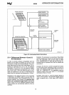
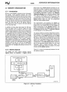
2.7.2 Address Spaces
The 80386 has three distinct address spaces:
logical, linear, and physical. A logical address
EFFECTIVE
ADDRESS
CALCULATION
(also known as a virtual address) consists of a se-
lector and
an
offset. A selector
is
the contents of a
segment register.
An
offset
is
formed
by
summing all
of the addressing components
(BASE,
INDEX,
DIS-
PLACEMENT) discussed
in
section 2.5.3 Memory
Addressing Modes
into
an
effective address. Since
each task on 80386 has a maximum of 16K
(2
14
-1)
selectors, and offsets can
be
4 gigabytes,
(2
32
bits) this gives a total of 2
46
bits or 64 terabytes of
logical address space per task. The programmer
sees this virtual address space.
The segmentation unit translates the
logical ad-
dress space into a 32-bit linear address space. If the
paging unit
is
not enabled then the 32-bit linear ad-
dress corresponds to the physical address. The
paging unit translates the
linear address space into
the
physical address space. The physical address
is
what appears
on
the address pins.
The primary difference between
Real
Mode and Pro-
tected Mode is how the segmentation unit performs
the translation of the
logical address into the linear
address.
In
Real Mode, the segmentation unit shifts
the selector left four bits and adds the result to the
offset to form the
linear address. While
in
Protected
Mode every selector has a
linear base address as-
sociated with it. The linear base address
is
stored
in
one of two operating system tables
(Le.
the Local
Descriptor Table or
Global Descriptor Table). The
selector's
linear base address
is
added to the offset
to form the final
linear address.
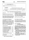
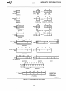
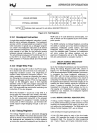
Figure
2-11
shows the relationship between the vari-
ous address spaces.
BE3-
BEQ
A31
-
A2
32
0
PHYSICAL
MEMORY
ADDRESS
LOGICAL
OR
SEGMENTATION
1----'3~2;C+1
PAGING
UNIT
14
VIRTUAL
ADDRESS
UNIT
LINEAR
(OPTIONAL
USE)
15
32
SEGMENT
REGISTER
t-"1'-;D;':ES;;C:;;'RI;;;PT;;:;O::-R
--+L
____
...J
ADDRESS
INDEX
Figure 2-11. Address Translation
21
PHYSICAL
ADDRESS
L-.._......I
231630-53