


80386
SYSTEM ADDRESS REGISTERS
47 32-BITLINEARBASEADDRESS
1615
LIMIT 0
~~~:I
I I
SYSTEM SEGMENT
REGISTERS DESCRIPTOR REGISTERS (AUTOMATICALLY LOADED)
~5
( 32-BIT LINEAR BASE ADDRESS
32-BIT SEGMENT LIMIT
ATTRIBUTES\
I
"
II
TR SELECTOR
LDTR SELECTOR
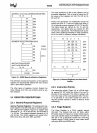
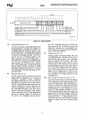
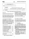
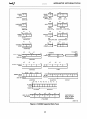
Figure 2-7. System Address and System Segment Registers
LDTR and TR
These registers hold the 16-bit selector for the LOT
descriptor and the TSS descriptor, respectively.
The
LOT
and TSS segments, since they are task-
specific segments, are defined by selector values
stored
in
the system segment registers. Note that a
segment descriptor register (programmer-invisible)
is
associated with each system segment register.
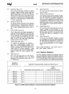
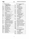
2.3.8 Debug and Test Registers
Debug Registers: The six programmer accessible
debug registers provide on-chip support for debug-
ging. Debug Registers
DRO-3 specify the four linear
breakpoints. The Debug Control Register DR? is
used to set the breakpoints and the Debug Status
Register DR6, displays the current state of the
breakpoints. The use of the debug registers
is
de-
scribed in section 2.12
Debugging support.
DEBUG REGISTERS
31
0
LINEAR BREAKPOINT ADDRESS 0
ORO
LINEAR BREAKPOINT ADDRESS 1
DR1
LINEAR BREAKPOINT ADDRESS 2 DR2
LINEAR
BREAKPOINT ADDRESS 3 DR3
Intel reserved.
Do
not define. DR4
Intel reserved.
Do
not define. DR5
BREAKPOINT STATUS
DR6
BREAKPOINT CONTROL
DR?
TEST
REGISTERS (FOR PAGE CACHE)
31
0
I TEST CONTROL
I
TR6
TR?
TEST STATUS
Figure 2-8. Debug and Test Registers
13
Test Registers: Two registers are used to control
the testing of the RAM/CAM (Content Addressable
Memories)
in
the Translation Lookaside Buffer por-
tion of the
80386. TR6 is the command test register,
and TR? is the data register which contains the data
of the Translation Lookaside buffer test. Their use
is
discussed in section
2.11
Testability.
Figure 2-8 shows the Debug
and
Test registers.
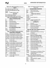
2.3.9 Register Accessibility
There are a few differences regarding the accessibil-
ity of the registers
in
Real and Protected Mode. Ta-
ble
2-1
summarizes these differences. See Section
4
Protected Mode Architecture for further details.
2.3.10 Compatibility
VERY IMPORTANT NOTE:
COMPATIBILITY WITH
FUTURE PROCESSORS
In
the preceding register descriptions, note cer-
tain
80386 register bits are undefined. When un-
defined bits are called out, treat them as fully
undefined. This
is
essential
for
your software
compatibility with future processorsl Follow the
guidelines below:
1)
Do not depend on the states of any unde-
fined bits when testing the values
of
defined
register bits. Mask them out when testing.
2)
Do
not depend
on
the states
of
any unde-
fined bits when storing them to memory or
another register.
3)
Do
not depend
on
the ability to retain infor-
mation written into any undefined bits.
4)
When loading registers always load the unde-
fined bits as zeros.