


80386
31
63
95
127
31302928272625242322212019181716151413121110987654321
0
1 1
1
1
0
1
1
0 o 0 0 0 1 1 1 1 0
1 0 0
1
1
0 0 o 0 0 0 0 0 1 1
0
0
1 0 0 0 1 1 1 1 0
0
1 0 1
0 1 1 1 1 1 1 0 0
1 1 1 1 1 o 0 1
1 1 1 1 1 1 1 1 1 1 1
1
1
1
1 1 1 1 1 1 1 1 1 1
1
1
1 1
1
1
1
1
0 0
0 0 0 0 0
000
o 0 0 0 0 o 0
0
0
0
0
0
0 0 0 0 0 0 0 o 0 0
1 1
1
1 1 1 1 1
'l'
etc.
'l'
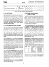
1/0
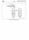
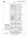
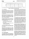
Ports Accessible: 2
--->
9,
12,
13,
15, 20
--->
24, 27, 33, 34, 40, 41, 48, 50,
52,
53, 58
--->
60, 62, 63, 96
--->
127
231630-71
Figure 4-15b. Sample
I/O
Permission
Bit
Map
4.4.5 Call
Ga~es
Gates provide protected, indirect CALLs. One of the
major uses of gates
is
to provide a secure method of
privilege transfers within a task.
Since the operating
system defines
all
of the gates
in
a system, it can
ensure that
all
gates only allow entry into a few trust-
ed
procedures (such
as
those which allocate memo-
ry,
or
perform I/O).
Gate descriptors follow the data access rules of priv-
ilege; that
is,
gates can be accessed
by
a task if the
EPL,
is
equal to or more privileged than the gate
descriptor's
OPL.
Gates follow the control transfer
rules of privilege and therefore may only transfer
control
to
a more privileged level.
Call Gates are accessed via a CALL instruction and
are
syntactically identical to calling a normal subrou-
tine. When
an
inter-level 386 call gate
is
activated,
the
following actions occur.
1.
Load CS:EIP from gate check for validity
2.
SS
is
pushed zero-extended to
32
bits
3.
ESP
is
pushed
4.
Copy Word Count 32-bit parameters from the
old stack to the new stack
5.
Push
Return address
on
stack
The procedure
is
identical for 286 Call gates, except
that 16-bit parameters are copied and 16-bit
regis-
ters are pushed.
Interrupt Gates and Trap gates work
in
a similar
fashion
as
the call gates, except there
is
no copying
of parameters. The only difference between Trap
and
Interrupt gates
is
that control transfers through
an
Interrupt gate disable further interrupts
(i.e.
the
IF
bit
is
set to 0), and Trap gates leave the interrupt
status unchanged.
4.4.6 Task Switching
A very important attribute of any multi-tasking/multi-
user operating systems is its ability to rapidly switch
between tasks or processes. The 80386 directly
supports this operation
by
providing a task switch
49
instruction
in
hardware. The 80386 task switch oper-
ation saves the entire state of the machine (all of the
registers, address space, and a
link to the previous
task), loads a new execution state, performs protec-
tion checks, and commences execution
in
the new
task,
in
about
17
microseconds. Like transfer of con-
trol via gates, the task switch operation
is
invoked
by
executing
an
inter-segment JMP
or
CALL instruction
which refers to a
Task State Segment (TSS), or a
task gate descriptor
in
the GOT or
LOT.
An
INT n
instruction, exception, trap, or external interrupt may
also invoke the
task switch operation if there
is
a
task gate descriptor
in
the associated lOT descriptor
slot.
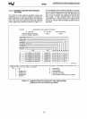
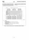
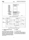
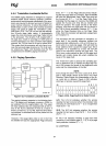
The
TSS descriptor points to a segment (see Figure
4-1
5)
containing the entire 80386 execution state
while a task gate descriptor contains a
TSS selector.
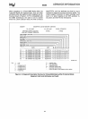
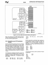
The 80386 supports both 286
and
386 style TSSs.
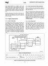
Figure 4-16 shows a 286
TSS.
The limit of a 386
TSS must be greater than 0064H (002BH for a 286
TSS), and can be
as
large as 4 Gigabytes.
In
the
additional
TSS space, the operating system
is
free
to store additional information such as the reason
the task
is
inactive, time the task has spent running,
and open files belong to the task.
Each task must have a
TSS associated with
it.
The
current
TSS
is
identified
by
a special register
in
the
80386
called the Task State Segment Register
(TR).
This register contains a selector referring to the task
state segment descriptor that defines the current
TSS. A hidden base and limit register associated
with TR are loaded whenever
TR
is
loaded with a
new selector. Returning from a task
is
accomplished
by
the IRET instruction. When IRET
is
executed,
control
is
returned to the task which was interrupted.
The current executing task's state
is
saved
in
the
TSS and the old task state
is
restored from its TSS.
Several bits
in
the flag register
and
machine status
word
(CRO)
give information about the state of a
task which are useful to the operating system. The
Nested Task (NT) (bit
14
in
EFLAGS) controls the
function of the
IRET instruction.
If
NT =
0,
the IRET
instruction performs the regular return; when NT =
1,
IRET performs a task switch operation back to the
previous task. The
NT
bit
is
set
or
reset
in
the follow-
ing fashion: