


Rev. D
Multi Pro 5700--D
Page 5 -- 7
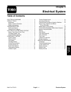
Electrical System
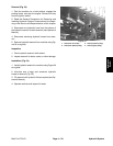
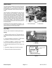
Component Testing
For accurate resistance and/or continuity checks, elec-
trically disconnect the component being tested from the
circuit (e.g. disconnect the ignition switch connectors
before doing a continuity check on the ignition switch).
NOTE: See the Kubota 05 Series Diesel Engine Ser-
vice Manual for more component testing information.
CAUTION
When testing electrical components for continu-
ity with a multimeter (ohms setting), make sure
that power to the circuit has been disconnected.
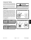
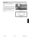
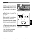
Ignition Switch
The ignition (key) switch has three positions (OFF, ON,
and START). Two ignition switches have been used on
Multi Pro 5700--D sprayers. Machines with serial num-
bers below 310000000 were equipped with a switch as
shown in Figure 4. Machines with serial numbers above
310000000 use a switch as shown in Figure 5. The
switch terminals are marked as shown in the appropri-
ate figure. The circuit logic of the ignition switches is
shown in the charts below. With the use of a multimeter
(ohms setting), the switch functions may be tested to de-
termine w hether continuity exists between the various
terminals for each switch position. Verify continuity be-
tween switch terminals.
Circuit identification formachines with serial number be-
low 310000000 (Fig. 4):
POSITION
CIRCUIT
OFF NONE
ON B+I+A, X+Y
START B+I+S
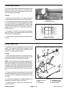
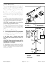
Circuit identification for machines with serial number
above 310000000 (Fig. 5):
POSITION
CIRCUIT
OFF NONE
ON B+C+F, D+E
START A+B+C
Figure 4
45
°
45
°
ON
START
OFF
A
B
S
Y
X
I
REAR VIEW
FRONT VIEW
SERIAL NUMBER BELOW 310000000
Figure 5
REAR VIEW
FRONT VIEW
A
B
C
D
E
F
START
OFF
RUN
45
o
45
o
SERIAL NUMBER ABOVE 310000000
Electrical
System