


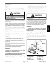
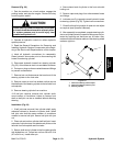

Removal (Fig. 45)
1. Park the machine on a level surface, engage parking
brake, and stop engine. Remove key from the ignition
switch.
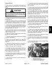
CAUTION
Rotate steering wheel and depress traction ped-
al in both forward and reverse to relieve hydrau-
lic system pressure and to avoid injury from
pressurized hydraulic oil.
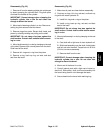
2. Operate all hydraulic controls to relieve hydraulic
system pressure.
3. Read the General Precautions for Removing and
Installing Hydraulic System Components at the begin-
ning of the Service and Repairs section of this chapter.
4. Label all hydraulic connections for reassembly pur-
poses. Clean hydraulic hose ends prior to disconnecting
the hoses.
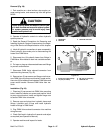
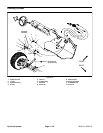
5. Remove fasteners that secure dash panel to front
hood (Fig. 47). Front edge of panel is secured with four
(4) screws and weldnuts. Sides of panel are fastened
with four (4) screws and flange nuts. Carefully slide dash
panel up steering column to allow access to steering
control valve.
6. Disconnect hydraulic hoses connected to the steer-
ing control valve. Allow hoses to drain into a suitable
container. Cap or plug openings of control valve and
hoses to prevent contamination.
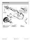
7. Support steering control valve to prevent it from fal-
ling during removal.
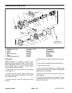
8. Loosen and remove four (4) cap screws that secure
steering column and steering control valve to machine
frame.
9. Slide steering valve from control column. Remove
control valve from machine.
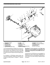
Installation (Fig. 45)
1. Slide steering control valve onto steering column.
Secure steering column and control valve to frame with
four (4) cap screws.
2. Remove caps and plugs from disconnected hoses
and fittings.
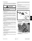
3. Lubricate new o–rings and connect hydraulic hoses
to steering control valve (Fig. 46). Tighten hose connec-
tions.
4. Position dash panel to front hood and secure with
fasteners (Fig. 47).
5. Check fluid level in hydraulic oil reservoir and adjust
as required (see Operator’s Manual).
6. After assembly is completed, operate steering cylin-
der to verify that hydraulic hoses and fittings are not con-
tacted by anything and that there are no leaks.
5
4
1
2
3
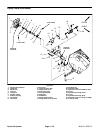
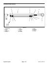
Figure 46
1. Steering control valve 4. Hyd hose (from pump)
2. Hyd hose (left turn) 5. Hyd hose (to oil cooler)
3. Hyd hose (right turn)
1
3
2
3
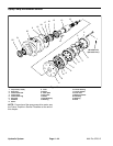
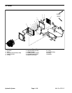
Figure 47
1. Steering column 3. Dash side screw
2. Dash front edge screw
Hydraulic
System
Multi Pro 5700–D Page 4 – 49 Hydraulic System