


Rev. D
Multi Pro 5700--DHydraulic System Page 4 -- 26
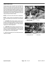
Adjust Relief Valve
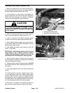
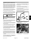
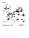
The spraypump drive circuit relief valve islocated on the
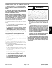
left side of the piston (traction) pump (Fig. 26). The
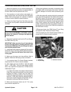
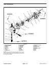
steering circuit relief valve is located under the suction
hose on the right side of the gear pump (Fig. 27). Relief
pressure should be tested before and afteradjusting the
relief valve (see Steering Circuit Relief Pressure Test
andSpray Pump DriveCircuit Relief PressureTest inthe
Testing section of this chapter). Adjustment of the relief
valve can be performed as follows:
NOTE: Do not remove the relief valve for adjustment.
NOTE: To gain access to the adjustment socket and
jamnut on thesteering circuit reliefvalve, remove plastic
cap.
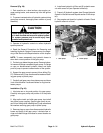
1. To increase relief pressure setting, loosen jam nut
on relief valve and turn the adjustment socket on the re-
lief valve in a clockwise direction. A 1/8 turnon the sock-
et will make a measurable change in relief pressure.
Tighten jam nut after adjustment.
2. To decrease pressure setting, loosen jam nut on re-
lief valve and turn the adjustment socket on the relief
valve in a counterclockwise direction. A 1/8 turn on the
socket will make a measurable change in relief pres-
sure. Tighten jam nut after adjustment.
3. Recheck spray pump drive circuit relief pressure and
readjust as needed.
1. Spray circuit relief valve
2. Relief valve body
3. Jam nut
Figure 26
3
2
1
1. Steering relief valve 2. Gear pump
Figure 27
1
2