


3. Chock front wheels and jack up rear of machine (see
Jacking Instructions in Operator’s Manual). Support
machine with jack stands or solid wood blocks.
4. Remove rear wheel assembly.
5. Remove hydraulic wheel motor (see Rear Wheel
Motors in Service and Repairs section of Chapter 4 –
Hydraulic System).
6. Disconnect brake cable from pull rod on brake.
NOTE: Be careful not to drop splined brake shaft as
brake assembly is removed.
7. Support brake assembly and remove four (4) flange
head screws that secure brake assembly to planetary
assembly. Remove brake assembly from machine.
8. Locate and remove splined brake shaft.
9. Complete brake inspection and repair.
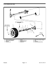
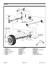
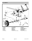
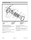
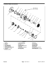
Installation (Fig. 6)
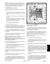
NOTE: The stepped end of the splined brake shaft
must be aligned toward the hydraulic wheel motor (Fig.
7).
1. Install splined brake shaft into brake assembly. Make
sure that splines engage rotating discs in brake assem-
bly.
2. Make sure that gasket surfaces of planetary and
brake assembly are clean. Position new gasket to brake
assembly.
3. Position brake assembly to machine, aligning
splined brake shaft with input shaft on planetary wheel
drive.
4. Make sure that gasket is properly positioned and
then install flange head screws (11) to secure brake as-
sembly to planetary assembly. Tighten screws in a
crossing pattern to a torque of 60 ft–lb (81 N–m).
5. Install brake cable to pull rod on brake assembly.
Brake cable end should be completely threaded onto
pull rod.
6. Install new o–ring on hydraulic wheel motor. Install
wheel motor (see Rear Wheel Motors in Service and Re-
pairs section of Chapter 4 – Hydraulic System).
Failure to maintain proper lug nut torque
WARNING
could result in failure or loss of wheel and may
result in personal injury.
7. Install wheel assembly with valve stem facing out.
Torque lug nuts from 70 to 90 ft–lb (95 to 122 N–m) to
secure wheel assembly.
8. Lower machine to ground.
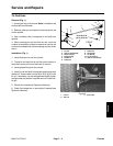
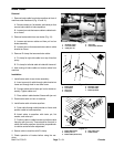
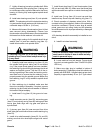
9. Make sure drain plug is installed in bottom of brake
assembly (Fig. 8). Fill planetary wheel drive/brake as-
sembly to proper level with SAE 85W–140 gear lube
(see Operator’s Manual).
10.Check and adjust brake cables for proper brake op-
eration (see Operator’s Manual).
3
1
2
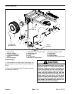
Figure 7
1. Splined brake shaft step 3. Planetary assembly end
2. Hydraulic motor end
2
3
1
Figure 8
1. Brake housing 3. Drain plug
2. Check
p
lu
g
Chassis
Multi Pro 5700–D Page 7 – 11 Chassis