


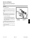

Fusible Link Harness
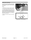
The Multi Pro 5700–D uses three (3) fusible links for cir-
cuit protection. These fusible links are located in a har-
ness that connects the starter B+ terminal to the main
wire harness (Fig. 41). If any of these links should fail,
current to the protected circuit will cease. Refer to wire
harness drawings in Chapter 8 – Electrical Diagrams for
additional fusible link information.
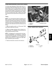
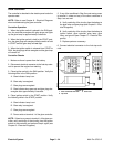
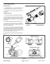
Use a multimeter to make sure that continuity exists be-
tween each terminal pin in connector P1 and connector
J1 at the starter (Fig. 42). If any of the fusible links are
open, replace the complete harness.
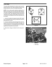
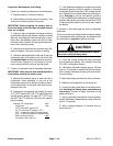
Figure 41
1
2
1. Starter motor 2. Fusible link harness
FUSIBLE LINK
FUSIBLE LINK
FUSIBLE LINK
Figure 42
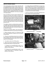
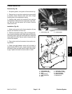
Diode Assembly
Two diode assemblies (Fig. 43) are used in the Multi Pro
5700–D wiring harness. Diode D1 is used to provide a
latching circuit for the cruise relay. Diode D2 is used for
circuit protection from voltage spikes that occur when
the cruise control coil is de–energized.
These diodes plug into the vehicle wire harness (see
wire harness drawings in Chapter 8 – Electrical Dia-
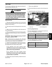
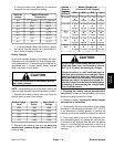
Figure 43
grams).
1. Diode assembly 3. Female terminal
2
1
3
2. Male terminal
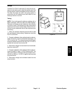
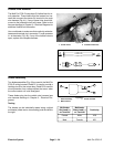
Testing
The diodes can be individually tested using a digital
multimeter (diode test or ohms setting) and the table to
the right.
Multimeter Multimeter
Red Lead (+) Black Lead (–)
Continuity
on Terminal on Terminal
Female Male YES
Male Female NO
Electrical System
Page 5 – 26
Multi Pro 5700–D