


Multi Pro 5700–D ChassisPage 7 – 13
Brake Cables
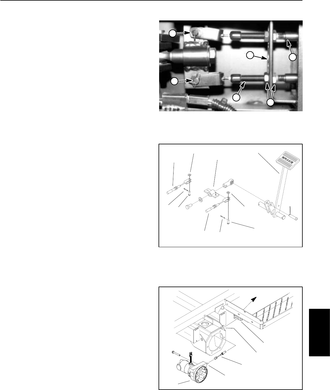
Removal
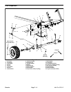
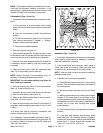
1. Remove brake cable from brake equalizer at front of
machine under floorboard (Fig. 10 and 11):
A. Remove cotter pin, flat washer, and clevis pin that
secure brake cable to brake equalizer.
B. Loosen jam nuts that secure cable to cable brack-
et on frame.
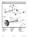
2. Remove brake cable from rear brake (Fig. 12):
A. Loosen and remove cable end from pull rod on
brake assembly.
B. Loosen jam nut that secures brake cable to cable
bracket on frame.
3. Remove R–clamp that secures brake cable:
A. R–clamp for right side cable is on top of traction
pump.
B. R–clamp for left side cable is inside left frame rail.
4. Note routing of brake cable and remove cable from
machine.
Installation
1. Install brake cable to rear brake assembly:
A. Insert rear end of cable through cable bracket on
frame and through hole in rear axle frame.
B. Connect cable end to brake pull rod on brake as-
sembly. Tighten cable end.
C. Place cable in cable bracket. Secure with jam nut.
2. Route brake cable to front of machine.
3. Install brake cable to brake equalizer:
A. Pass cable through cable bracket on frame and
position cable to brake equalizer.
B. Attach cable to equalizer with clevis pin, flat
washer, and cotter pin.
C. Position cable to cable bracket and adjust cable
free play with jam nuts. There should be no slack in
cable and brake equalizer should be perpendicular
to vehicle centerline after adjustment.
4. Secure cable to machine with R–clamp.
5. Check operation of brakes before using the ma-
chine.
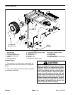
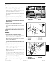
1. RH brake cable
2. LH brake cable
3. Cable jam nut
4. Clevis pin
5. Frame cable bracket
Figure 10
PHOTO TAKEN FROM BELOW
1
4
4
2
5
3
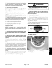
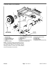
1. Brake pedal
2. Flat washer
3. Clevis pin
4. Cotter pin
5. RH brake cable
6. LH brake cable
7. Brake equalizer
Figure 11
6
5
4
7
2
3
3
1
2
4
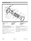
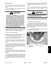
1. Brake (RH shown)
2. Brake pull rod
3. Brake cable (RH shown)
4. Axle frame hole
5. Cable bracket
Figure 12
4
3
1
2
5
Chassis