


Multi Pro 5700--DHydraulic System Page 4 -- 34
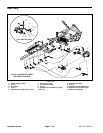
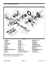
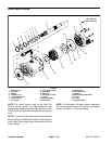
Piston (Traction) Pump
Figure 31
1. Piston (traction) pump
2. O--ring
3. Hydraulic adapter
4. O--ring
5. Hydraulic tee fitting
6. Hydraulic hose (to reservoir)
7. O--ring
8. 90
o
hydraulic fitting
9. O--ring
10. Hydraulic hose (piston pump suction)
11. O--ring
12. Gear pump
13. Hydraulic hose (gear pump suction)
14. Cap screw (2 used)
15. Flat washer (2 used)
16. Hydraulic hose (to LH wheel motor)
17. Hydraulic hose (to RH wheel motor)
18. 45
o
hydraulic fitting
19. Straight fitting
20. O--ring
21. Hydraulic hose (to oil filter)
22. O--ring
23. 90
o
hydraulic fitting
24. Hydraulic hose (from oil filter)
25. Hydraulic hose (from wheel motors)
26. Hydraulic hose (to steering control)
27. Hydraulic tee fitting
28. Hydraulic hose (to PWM valve)
29. Hydraulic hose
30. O--ring
31. 90
o
hydraulic fitting
32. O--ring
33. Seal kit
34. Relief valve
35. Relief valve body
36. Hydraulic adapter
37. Cap screw (2 used)
38. Lock washer (2 used)
39. Flat washer (2 used)
40. O--ring
LEFT SIDE OF PUMP
NOTE: ILLUSTRATION FROM
BOTTOM OF MACHINE
1
5
9
4
7
2
3
6
8
10
14
18
13
16
11
12
15
17
19
23
22
20
21
24
25
26
27
28
29
30
31
32
33
34
35
36
37
38
39
40
7
7
9
7
7
9
4
4
22
4
4
32
2
Antiseize
Lubricant
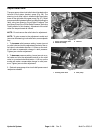
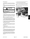
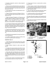
Removal (Fig. 31)
1. Park machine on a level surface, stop engine, en-
gage parking brake, and remove key from the ignition
switch.
2. To prevent contamination of hydraulic system during
pump removal, thoroughly clean exterior of pump as-
sembly.
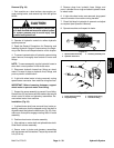
CAUTION
Rotate steering wheeland depress traction ped-
al in both forward and reverse to relieve hydrau-
lic system pressure and to avoid injury from
pressurized hydraulic oil.