


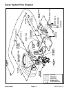
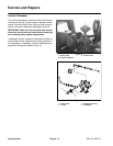
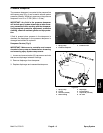
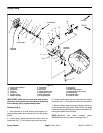

Spray System Operation
The Multi Pro 5700–D spray system uses a positive dis-
placement diaphragm pump to move spray solution
from the spray tank to the boom nozzles. The spray
pump is self–priming and has a dry crankcase.
The downward stroke of the pumps’ two connecting
rods and diaphragms create suction to allow fluid to be
drawn from the spray tank to the pump via the suction
tube, suction strainer, hoses, and connectors. A suction
dampener placed in the suction line dampens suction
pulses to smooth suction flow. Suction valves positioned
in the pump valve chamber prevent fluid from being
pumped back into the suction line. Leaks in the suction
line will cause system problems and often will be indi
-
cated by erratic suction line jumping and excessive
pump noise.
Once to the pump, the fluid is pushed by the upward
stroke of the pumps’ two connecting rods and dia
-
phragms to the pressure side of the spray system
through hoses, connectors, control valves, and spray
nozzles. A pressure dampener at the pump outlet
smooths system pressure pulsation. Pressure valves
positioned in the pump head prevent fluid from being
drawn back into the pump. Maximum pressure in the
system is limited by a pressure relief valve located in the
tank. A pressure gauge on the dash panel indicates
spray system pressure.
Battery current for spray system fuses, switches, valve
motors, and other components is provided by the acces
-
sory solenoid when the machine ignition switch is in the
RUN position. For spray system electrical component
information and test procedures, see Chapter 5 – Elec
-
trical System.
The machine operator controls the spray system on the
Multi Pro 5700–D with electrical switches located on the
spray console. Switches include a spray pump on/off
switch, an application rate (increase/decrease) switch,
an agitation control switch and three boom control
switches. These switches control the PWM Valve, the
agitation control valve and three boom control valves.
Additionally, a master (foot) boom valve switch allows
the operator to turn off/on all three boom sections.
The spray pump is directly coupled to and driven by a hy-
draulic motor. Flow from the hydraulic gear pump to the
motor is controlled by the Pulse Width Modulated
(PWM) Valve. Based on available current (mA) from the
spray pump application rate (increase/decrease)
switch, the PWM spool valve directs gear pump flow to
the spray pump hydraulic motor. This hydraulic flow
causes the motor to rotate the spray system pump for
spray system operation.
When the spray pump is on, application rate (increase/
decrease) switches allow the operator to adjust electri
-
cal current to the PWM Valve solenoid. Higher current
(rate increase) to the PWM solenoid increases hydraulic
flow to the spray pump motor and results in a higher
spray pump speed with more output/pressure. Lower
current (rate decrease) to the PWM solenoid decreases
hydraulic flow to the spray pump motor and results in a
lower spray pump speed with less output/pressure. De
-
sired spray pump pressure should be based on boom
nozzle selection and ground speed (see Nozzle Selec
-
tion Guide (Toro Form No. 3351–389) for information re-
garding boom nozzle selection).
When the agitation switch is ON, the switch light is illumi-
nated and the agitation control valve is opened. This
open valve directs system flow to three agitation nozzles
in the spray tank. When the agitation switch is OFF, the
agitation control valve is closed so no flow is available
for tank agitation nozzles.
When a boom control switch (left, center or right) is ON,
the switch light is illuminated and the boom control valve
for that boom is opened. This open valve directs system
flow to the spray nozzles located on the boom section.
When a boom control switch is OFF, the boom control
valve is closed so no flow is available to that spray boom.
A manually adjustable boom bypass valve is incorpo-
rated in each of the boom control valves. Proper adjust-
ment of the boom bypass valves prevents system
pressure changes when a boom section is shut off. Flow
from the boom bypass valves is directed back to the tank
(boom bypass).
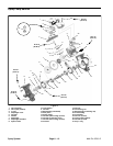
An optional Pro Control Spray System is available for
the Multi Pro 5700–D. This system includes a console
computer and an inline flowmeter to control the spray
pressure system. The flowmeter is positioned in the
pressure side of the spray system directly before the
boom control valves. The flowmeter measures spray
boom flow. The Pro Control computer determines sys
-
tem application rate based on operator programming
and inputs from the flowmeter and the ground speed
sensor located in the right rear wheel motor. Additional
Pro Control information can be found in the Pro Control
Spray System Operator’s Manual.
NOTE: When a vehicle is equipped with the optional
Pro Control Spray System, the balancing valves on all
boom valve motors must be fully closed.
Spray
System
Multi Pro 5700–D
Page 6 – 5
Spray System