


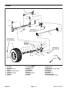
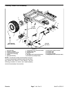
Disassembly (Fig. 5)
1. Park machine on a level surface, stop engine, en-
gage parking brake, and remove key.
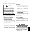
CAUTION
ing other service, use correct blocks, hoists,
and jacks. Make sure machine is parked on a
ments that may interfere with the safe and
block wheels. Use jack stands or solid wood
jack stands, the machine may move or fall,
When changing attachments, tires, or perform-
solid, level surface such as a concrete floor.
Prior to raising machine, remove any attach-
proper raising of the machine. Always chock or
blocks to support the raised machine. If the ma-
chine is not properly supported by blocks or
which may result in personal injury.
2. Jack front of machine off ground (see Jacking In-
structions in Operator’s Manual). Support machine to al-
low front suspension to hang freely from machine.
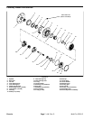
3. Remove front wheel assembly (see Front Wheels
and Hubs).
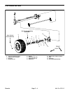
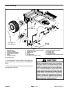
4. Disassemble front suspension as needed using Fig-
ure 5 as a guide.
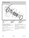
A. If wheel hub requires removal, see Front Wheels
and Hubs Removal in this section. If spindle requires
removal, see Spindles in this section.
B. When removing leaf springs, support axle to pre-
vent it from falling. Loosen fasteners that secure
springs to frame attachment points. Loosen and re-
move cap screws and locknuts that secure spring
plate. Remove shackles, bushings, shoulder bolts,
lock washers and hex nuts from spring and frame.
Remove leaf springs from machine.
C. If front axle removal is required, remove steering
cylinder from axle (see Steering Cylinder in Service
and Repair Section of Chapter 4 – Hydraulic Sys-
tem).
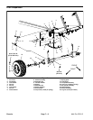
Assembly (Fig. 5)
1. Assemble front suspension using Figure 5 as a
guide.
A. When installing suspension components, loosely
install all fasteners before tightening any of the fas-
teners.
B. If wheel hub was removed, see Front Wheels and
Hubs Installation in this section. If spindle was re-
moved, see Spindles in this section.
NOTE: When installing leaf springs, make sure front
axle and spring plate are centered on the screw head
and nut that fasten spring leaves.
IMPORTANT: If leaf spring replacement is need-
ed, always replace both springs for proper ve-
hicle performance.
C. To install leaf springs, attach springs to frame with
shackles, bushings, shoulder bolts, lock washers
and hex nuts without tightening fasteners. Install
spring plate to top of spring assembly with curved
edge toward spring. Install and tighten cap screws
and lock nuts in a crossing pattern until spring plate,
leaf spring and axle contact. Fully tighten fasteners
that secure springs to frame. Torque lock nuts that
secure spring plate 35 ft–lb (47 N–m) using a cross-
ing pattern.
D. When installing shock absorbers, make sure that
spacer is positioned between shock and frame at-
tachment point.
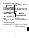
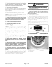
Failure to maintain proper lug nut torque
WARNING
could result in failure or loss of wheel and may
result in personal injury.
2. Install wheel with valve stem facing out and secure
with lug nuts. Torque lug nuts evenly in a crossing pat-
tern from 55 to 75 ft–lb (75 to 102 N–m).
3. Lower machine to ground.
4. Lubricate suspension grease fittings (see Operator’s
Manual).
5. Check front wheel toe–in and adjust if necessary
(see Operator’s Manual).
6. Check front suspension and steering operation.
Make sure that components do not contact hoses and/or
wires.
Chassis
Multi Pro 5700–D Page 7 – 9 Chassis