


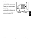
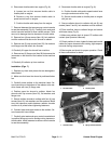


10.Remove throttle cable from engine (Fig. 14).
A. Loosen jam nut that secures throttle cable to
throttle plate on engine.
B. Remove e–ring that secures throttle cable to
speed control lever on engine.
C. Position throttle cable away from the engine.
11. Note location of any cable ties used to secure the wir-
ing harness, fuel lines or hydraulic hoses to the engine
assembly. Remove cable ties attached to engine as-
sembly.
IMPORTANT: Support engine assembly to prevent
it from falling and being damaged during removal.
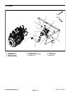
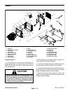
12.Remove flange nuts, snubbing washers and cap
screws securing the engine brackets to the machine
frame (Fig. 11).
IMPORTANT: Make sure not to damage the engine,
fuel hoses, hydraulic lines, electrical harness or
other parts while removing the engine assembly.
13.Using a hoist or lift, carefully lower engine from the
machine.
14.If necessary, remove engine brackets from the en-
gine and engine mounts from frame.
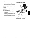
Installation (Fig. 10)
1. Locate machine on a level surface with key removed
from the ignition switch. Raise machine to allow engine
to be raised into frame.
2. Make sure that all parts removed from the engine
during maintenance or rebuilding are reinstalled to the
engine.
3. If engine brackets were removed from engine, se-
cure brackets to engine with cap screws and lock wash-
ers.
4. If engine mounts were removed from frame, secure
mounts to frame with cap screws and flange nuts.
IMPORTANT: Support engine assembly to prevent
it from falling and being damaged during installa-
tion.
IMPORTANT: Make sure not to damage the engine,
fuel hoses, hydraulic lines, electrical harness or
other parts while installing the engine assembly.
5. Using a hoist or lift, carefully raise engine assembly
from under machine and position to frame. Insert cap
screws through engine brackets and motor mounts from
above (Fig. 11). Install flange nuts on cap screws and
tighten nuts.
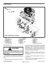
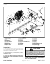
Kubota Diesel Engine
2
3
4
5
1
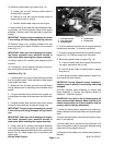
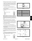
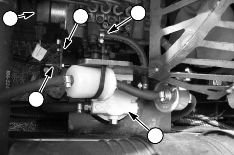
Figure 14
1. Fuel stop solenoid 4. Throttle cable
2. Fuel supply hose 5. Throttle plate
3. Water/fuel filter
6. Connect machine wire harness to engine electrical
components (see step 7 in removal procedure).
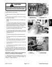
7. Connect fuel supply hose to the fuel injector pump on
engine (Fig. 14). Remove clamp from fuel hose.
8. Reconnect throttle cable to engine (Fig. 14).
A. Position throttle cable end to speed control lever
on engine and secure with e–ring.
B. Secure throttle cable to throttle plate on engine
with jam nut.
9. Install upper and lower radiator hoses to engine. Se-
cure hoses with hose clamps.
IMPORTANT: During hydraulic pump installation,
support pump to prevent it from falling and being
damaged.
10.Install hydraulic pump assembly to engine (see
Pump Assembly in Service and Repairs section of
Chapter 4 – Hydraulic System).
IMPORTANT: Any leaks in the air intake system will
cause serious engine damage. Make sure that all air
cleaner components are in good condition and are
properly secured during reassembly.
11. Install air cleaner hose to engine and air cleaner as-
sembly. Make sure that hose clamps are properly tight-
ened.
12.Install exhaust system (see Exhaust System Instal-
lation in this section).
13.Install cable ties to secure the wiring harness, fuel
lines and hydraulic hoses to the engine assembly using
notes taken during engine removal.
14.Properly fill the radiator with coolant (see Operator’s
Manual).
Multi Pro 5700–D
Page 3 – 14