


Gear Pump Flow Test
Output from the gear pump is divided by a priority flow
divider to allow priority flow to the steering circuit and
secondary flow to the spray pump drive circuit. To test
gear pump flow, testing of both circuits is required. Total
gear pump flow is the combined flow from the two cir-
cuits. If a problem is suspected in one of the two circuits,
flow for that circuit should be measured to determine if
the problem is pump related or is involved with other cir-
cuit components.
1. Make sure hydraulic oil is at normal operating tem-
perature by operating the machine for approximately 10
minutes. Make sure the hydraulic tank is full.
2. Park machine on a level surface, stop engine, en-
gage parking brake, and remove key from the ignition
switch. After turning engine off, operate all hydraulic
controls to relieve hydraulic system pressure.
CAUTION
of this section.
Prevent personal injury and/or damage to equip-
ment. Read all WARNINGS, CAUTIONS, and Pre-
cautions for Hydraulic Testing at the beginning
IMPORTANT: Make sure that the oil flow indicator
arrow on the flow meter is showing that the oil will
flow from the pump, through the tester, and into the
hydraulic hose.
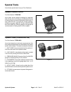
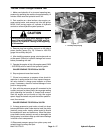
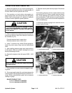
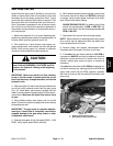
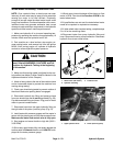
3. With the engine off, clean hose fitting and disconnect
one of the circuit pressure hoses from the gear pump
(Fig. 16). Install tester with pressure gauges and flow
meter in series between the gear pump and the discon-
nected hose. Make sure the tester flow control valve
is open.
4. After installing tester, start engine and run at idle
speed. Check for hydraulic leakage and correct before
proceeding with test.
IMPORTANT: The gear pump is a positive displace-
ment type. If pump flow is completely restricted or
stopped, damage to the gear pump, tester, or other
components could occur.
5. Operate the engine at high idle speed (3050 – 3150
RPM). Verify engine speed with a phototac.
6. While watching tester pressure gauges, slowly close
flow control valve on the tester until 800 PSI is obtained
on gauge. Verify engine speed continues to be within
spec. Record flow meter reading.
GAUGE READING TO BE: For steering circuit, flow
should be approximately 3 GPM at 800 PSI. For
spray motor circuit, flow should be approximately 9.5
GPM at 800 PSI.
7. Open tester flow control valve and stop engine.
NOTE: Relief pressure for steering and/or spray pump
drive circuits can be determined with the tester posi-
tioned as described in this test.
8. Remove tester and reinstall disconnected hose.
Complete steps 3 through 6 for other circuit hose.
9. If the total of the two flows is less than 12.5 GPM or
a pressure of 800 PSI could not be obtained, check for
restriction in pump suction line. If suction line is not re-
stricted, remove gear pump and repair or replace as
necessary.
If the total of the two flows is 12.5 GPM but individual cir-
cuit flow is incorrect (e.g. steering circuit has 6 GPM and
spray motor circuit has 6.5 GPM), suspect a problem
with one of circuits or with the priority flow divider in the
gear pump.
2
1
Figure 16
1. Steering circuit pressure hose
2. Spray motor circuit pressure hose
Hydraulic
System
Multi Pro 5700–D Page 4 – 19 Hydraulic System