


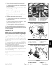

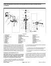
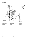
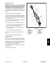
3. Assemble spindle section by reversing disassembly
process. Align green indicator tab on spindle to slot in
spindle housing. Install screw into bottom of spindle to
secure assembly. Torque screw 70 in–lb (7.9 N–m).
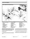
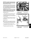
4. Position spindle section on motor section so that
green indicator on spindle section is opposite the motor
hand grip. Secure spindle section to motor section with
four phillips head screws (item 15).
5. Replace rear housing to valve motor.
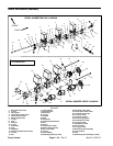
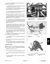
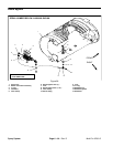
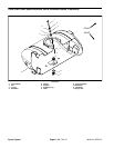
6. Position the motor and spindle section assembly to
the manifold assembly. The motor hand grip and boom
supply hosebarb on manifold should be on the same
side of the assembly. Install the fork (item 29) to secure
the motor and spindle sections to the manifold.
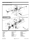
7. Assemble valve motor assembly. (see Boom Valve
Motor Assembly or Agitation Valve Motor Assembly in
this section).
8. Install valve motor assembly to machine (see Spray
Control in this section).
9. Operate spray system and check for leaks.
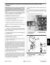
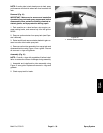
Spray System
Page 6 – 28
Multi Pro 5700–D