


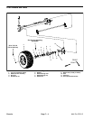
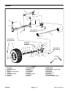

Removal (Fig. 3)
1. Park machine on a level surface, stop engine, en-
gage parking brake, and remove key from the ignition
switch.
CAUTION
When changing tires or performing other ser-
vice, use correct blocks, hoists, and jacks.
Make sure machine is parked on a solid, level
machine. Always chock or block wheels. Use
raised machine. If the machine is not properly
surface such as a concrete floor. Prior to rais-
ing machine, remove any attachments that may
interfere with the safe and proper raising of the
jack stands or solid wood blocks to support the
supported by blocks or jack stands, the ma-
chine may move or fall, which may result in per-
sonal injury.
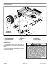
2. Jack front wheel off the ground (see Jacking Instruc-
tions in Operator’s Manual). Chock front and rear of oth-
er wheels.
3. Remove lug nuts and front wheel assembly.
4. Carefully pry dust cap from wheel hub.
5. Remove cotter pin from front spindle.
6. Remove slotted hex nut and washer that secures
wheel hub to spindle. Slide wheel hub with bearings
from spindle.
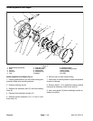
7. If required, disassemble wheel hub:
A. Pull seal out of the wheel hub.
B. Remove bearings from both sides of wheel hub.
Clean bearings in solvent. Clean inside of the hub.
C. Inspect wheel bearings. Check the bearings and
cups for wear, pitting, or other noticeable damage.
Replace worn or damaged parts.
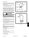
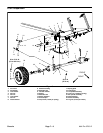
Installation (Fig. 3)
1. Clean all parts thoroughly before reassembly.
2. If wheel bearings were removed from wheel hub, as-
semble wheel hub:
A. If bearing cups were removed from the wheel
hub, press inner and outer cups into the hub until
they seat against the hub shoulder.
B. Pack both bearings with grease. Install greased
inner bearing into the cup on inboard side of the
wheel hub.
C. Fill hub approximately 50% full of grease.
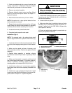
IMPORTANT: The lip seal must be pressed in so
it is flush with the end of the hub. The lip of the
seal must face the bearing.
D. Lubricate the inside of the new lip seal and press
it into the wheel hub.
3. Install the wheel hub onto the spindle shaft taking
care to not damage seal.
4. Install greased outer bearing cone, washer, and
slotted hex nut onto spindle shaft.
5. Rotate the wheel hub by hand and torque the slotted
hex nut from 75 to 180 in-lb (8.5 to 20.3 N–m) to seat
bearing. Loosen nut until it is away from washer and hub
has end play. Finally, tighten slotted hex nut from 15 to
20 in–lbs (1.7 to 2.3 N–m) while rotating hub.
6. Install cotter pin through spindle shaft hole. Install
dust cap to hub.
Failure to maintain proper lug nut torque
WARNING
could result in failure or loss of wheel and may
result in personal injury.
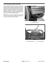
7. Install wheel assembly with valve stem facing out
and secure with lug nuts. Torque lug nuts evenly in a
crossing pattern from 55 to 75 ft–lb (75 to 102 N–m).
8. Lower machine to ground.
Chassis
Multi Pro 5700–D Page 7 – 5 Chassis