


Steering Circuit Relief Pressure Test
1. Make sure hydraulic oil is at normal operating tem-
perature by operating the machine for approximately 10
minutes. Make sure the hydraulic tank is full.
2. Park machine on a level surface, stop engine, en-
gage parking brake, and remove key from the ignition
switch. After turning engine off, operate all hydraulic
controls to relieve hydraulic system pressure.
CAUTION
of this section.
Prevent personal injury and/or damage to equip-
ment. Read all WARNINGS, CAUTIONS, and Pre-
cautions for Hydraulic Testing at the beginning
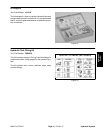
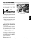
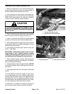
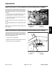
3. Clean hose fitting and disconnect lower pressure
hose from the left side of the gear pump (Fig. 17).
4. Install T–connector with 5,000 PSI pressure gauge
in series with the pump and the disconnected hose.
5. After installing pressure gauge, start engine and run
at idle speed. Check for hydraulic leakage and correct
before proceeding with test.
6. Start engine and adjust engine speed to high idle
(3050 – 3150 RPM).
IMPORTANT: Hold steering wheel at full lock only
long enough to get a system pressure reading.
Holding the steering wheel against the stop for an
extended period will damage the steering motor.
7. Watch pressure gauge carefully while turning the
steering wheel completely in one direction (full steering
lock) and holding momentarily.
8. System pressure should be approximately 1000 PSI
as the relief valve lifts. Return steering wheel to the cen-
ter position.
9. Slow engine speed and turn off machine. Record test
results.
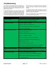
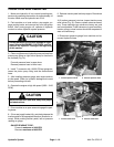
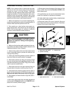
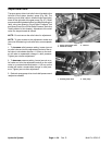
10.If relief pressure is incorrect, inspect for worn, stuck,
or out of adjustment relief valve. Steering relief valve is
located under the suction hose on the right side of the
gear pump (Fig. 18). For adjustment procedure, see Ad-
just Relief Valve in the Adjustments section of this Chap-
ter. After adjustment, retest relief valve pressure.
11. Disconnect T–connector and pressure gauge from
gear pump and hose. Reconnect hose to the pump.
1
2
Figure 17
1. Steering circuit pressure hose
2. Spray motor circuit pressure hose
1
2
Figure 18
1. Steering relief valve 2. Gear pump suction hose
Hydraulic System Page 4 – 20 Multi Pro 5700–D