


Wheel Motor Efficiency: Case Drain Test
NOTE: Over a period of time, a wheel motor can wear
internally. A worn motor may by–pass oil to its case drain
causing the motor to be less efficient. Eventually,
enough oil loss will cause the wheel motor to stall under
heavy load conditions. Continued operation with a worn,
inefficient motor can generate excessive heat, cause
damage to seals and other components in the hydraulic
system and affect overall machine performance.
1. Make sure hydraulic oil is at normal operating tem-
perature by operating the machine for approximately 10
minutes. Make sure the hydraulic tank is full.
2. Park machine on a level surface, stop engine, en-
gage parking brake, and remove key from the ignition
switch. After turning engine off, operate all hydraulic
controls to relieve hydraulic system pressure.
CAUTION
of this section.
Prevent personal injury and/or damage to equip-
ment. Read all WARNINGS, CAUTIONS, and Pre-
cautions for Hydraulic Testing at the beginning
3. Make sure that traction pedal is adjusted to the neu-
tral position (see Adjust Traction Pedal for Neutral in the
Adjustments section of this Chapter).
4. Attach a heavy chain to the rear of the machine frame
and an immovable object to prevent the machine from
moving during testing.
5. Chock rear wheel being tested to prevent rotation of
the wheel. Make sure parking brake is engaged.
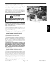
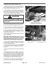
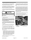
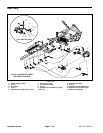
6. Disconnect hydraulic tee fitting and pressure hose
from rear wheel motor that is not being tested (Fig. 20).
Cap disconnected fitting and hose. Plug ports in wheel
motor to prevent contamination.
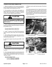
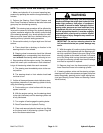
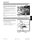
7. Disconnect hose from the upper hydraulic fitting on
the right side of the piston (traction) pump (Fig. 21).
8. Install tester with pressure gauges and flow meter in
series with the piston pump and the disconnected hose.
Make sure the tester flow control valve is fully open.
9. Start engine and move throttle to high idle (3050 –
3150 RPM).
10.Sit on seat, apply brakes fully, and slowly depress the
traction pedal in forward direction until 1000 PSI is dis-
played on the tester pressure gauge.
11. Wheel motor internal leakage will be shown on flow
meter in GPM. Flow should be less than 2 GPM for the
tested wheel motor.
12.If specifications are not met, the tested wheel motor
needs to be repaired or replaced as necessary.
13.If other wheel motor requires testing, complete steps
5 to 14 for the remaining motor.
14.Disconnect tester from pump hydraulic fitting and
hose. Reconnect hose to pump connection. Reconnect
hydraulic lines to rear wheel motor.
1
2
3
Hydraulic
System
Figure 20
1. Wheel motor (RH shown) 3. Pressure hose
2. Hydraulic tee fitting
1
2
Figure 21
1. Upper hydraulic hose 2. Piston (traction) pump
Multi Pro 5700–D Page 4 – 23 Hydraulic System